29
5–1. HANDLING
• Remove the torque converter retaining strap when the transmission is in
position for installation.
5–2. COUPLING TO ENGINE
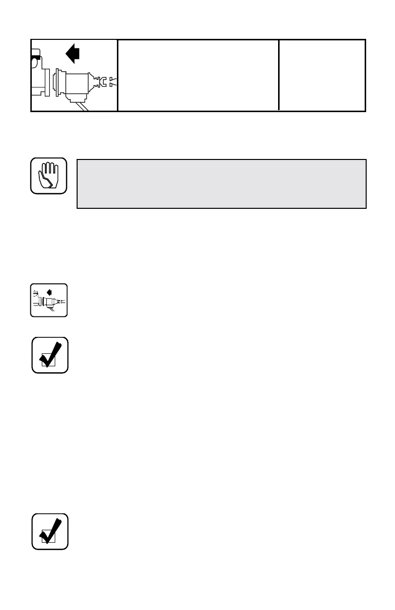
• Align the flexplate and torque converter so that the drive bolts (used
on all models except AT 543) or nuts (AT 543) can be installed
(Figure 2–1). A pilot tool (Figure 5–1) can be used to maintain
alignment on all AT models with drive bolts.
• Lubricate the center pilot bore and converter nose pilot with molybdenum
disulfide grease.
• Push the transmission toward the engine while guiding the pilot boss on the
drive cover into the center bore and the pilot diameter of the transmission
housing into the flywheel housing bore. If interference is encountered, move
the transmission away from the engine and investigate the cause.
• Install the ten or twelve bolts that secure the transmission housing to the
engine flywheel. Bolts must be installed in the two uppermost bolt holes.
Tighten the bolts to the torque specified by the vehicle manufacturer.
CAUTION: The transmission must be handled very carefully after
the torque converter retaining strap is removed to avoid separating the
torque converter from the transmission. Keep the transmission level or
the rear slightly lower than the front at all times.
NOTE: If a starter ring gear is welded to the flexplate, the complete
drive connection should be statically or dynamically balanced to
reduce vibration.
NOTE: The drive cover nuts (AT 543) must be self-locking and
capable of producing a tensile load of 8000 lb (36 kN). A nut that
meets these requirements is Allison P/N 23014107.
INSTALLING
TRANSMISSION INTO
VEHICLE
SECTION
V
 Loading...


