EasyManua.ls Logo

Allmatic AV - User Manual

Default Icon
6 pages
Print Icon
To Next Page IconTo Next Page
Loading...
ITA ENG FRA ESP DEU POR
6-1622081 REV.12 23/09/2020 1 / 6
Control unit AV and AV1
1. Introduction.
LIT LIGHT = FUNCTION ENABLE
3. Electrical connections.
J5 jumper configuration for limit switch or
boton selection.
J5 close: Limit switch selection.
J5 open : Button selection
CONTROL UNTI WITH EXTRACTIBLE MEMORY
Control unit for a motor in alternatine current with torque adjuster (AV1), output contact for limit switch or Open/close bottons, selectable, output con-
tact for photo dispositive, stop button, step-by-step, with radio modular and memory of expansion and possibilità to install an additional card for courte-
sy light and electrolock (AV1).
This control unit has been designed for the automation of rolling shutters, shutters and sliding doors.
2. Configuration.
J2
J3
J4
J5
J1
ATTENTION!! N.C. CONTACTS NOT USED MUST BE
JUMPED TO THE COMMON WIRE LIKE SHOW IN THE
FOLLOWING FIGURE.
The contact 9 and 10 must be jumped to the common only if
jumper J5 is close and the photocellule are not connected.
Optional torque
regulator
(only with AV1).
MIN
MAX
230 VAC
Card options
(only with AV1).
Vac/dc
1 2 3
4
ELS
LC
Vac/dc
FUNCTION SELECTION PRESENT
ON AV AND AV1
( See page 4 ).
J1
Step-by-step / open-close func-
tion selection.
J2
Normal / deadman function
selection.
J3 Fixe code / rolling code selection.
J4
Condominium function enable /
disabile selection.
J5
Limit-switch or button use
selection.
230 Vac
NEUTRAL
PHASE
Photocells power supply
24 Vac 1.5 W MAX
If the torque regulator is used, connect the flashing light (with
self-blinking card) to the output of the torque regulator
Connection for blinker
BRO LIGHT 220 (with
self-blinking card) without
torque regulator
Question and Answer IconNeed help?

Do you have a question about the Allmatic AV and is the answer not in the manual?

Allmatic AV Specifications

General IconGeneral
BrandAllmatic
ModelAV
CategoryControl Unit
LanguageEnglish

Summary

Introduction

Control Unit Configuration

AV1 Card Options

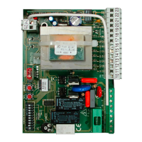
Configuration options specific to AV1 models.

Function Selection Jumpers (J1-J5)

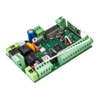
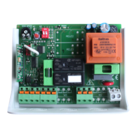
Overview of J1-J5 jumper settings for various functions.

LIT LIT Function Enable Indicator

Describes the meaning of the LIT LIT indicator.

Electrical Connections

J5 Jumper Configuration

J5 jumper settings for limit switch or button control.

Wiring Diagram Overview

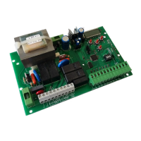
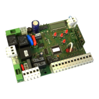
Diagram showing electrical connections for terminals 1-15.

Learning Procedures

Remote Control Pairing

Procedure for setting remote controls.

Gate Work Time Programming

Programming the gate's operational duration.

Configuration Settings

Automatic Closure Setup

Programming automatic reclosure time.

Functionality Settings

Pedestrian Mode Activation

How to enable and configure pedestrian mode.

Electric Lock Output Control

Steps to activate and deactivate the electric lock output.

Variable Code System Setup

How to set up Allmatic or customized variable code decoding.

Programming Management

Exiting Programming Mode

Describes how to exit programming.

Control Unit Reset

Procedure to reset the control unit to factory settings.

Advanced Jumper Configurations

Jumper Functions Explained

Details on jumper settings for personalization.

J1: Impulse;Pedestrian Operation

J1 settings for impulse mode and pedestrian function.

J2: Normal;Person Present Operation

J2 settings for normal or person present modes.

J3: Fixed;Variable Code Selection

J3 for fixed or variable code transmitter setting.

J4: Condominium Mode Control

J4 controls the condominium master function.

Additional Card and Technical Data

Additional Card Connector Details

Diagram of the additional card connector.

Technical Specifications Summary

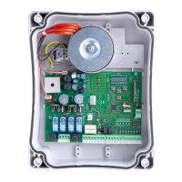
Key technical details of the control unit.

Guarantee and Disposal

Product Guarantee Terms

Terms and conditions of the producer's guarantee.

Product Disposal Instructions

Guidelines for proper product disposal.

Related product manuals