9
TOOLS REQUIRED
The following tools and materials are required for proper
installation of the operator:
1. Two 3/4" wrenches. (For tightening hex nuts on the
c h a i n t a k e - u p b o l t s . )
2. Chain cutting tool. (For adjusting chain length.)
3. Wire cutter, stripper and crimping tools. (For attaching
accessory equipment to the control box barrier strip.)
4. Standard screwdriver. (For junction box face plate.)
5. Very small standard screw driver. (For adjusting
controller board trimmer potentiometers.)
6. Phillips head screwdriver. (For control box face plate.)
7. Electric arc welder or an electric drill with a 3/8" bit.
(For attaching chain brackets to gate.)
8. Several feet of 18 AWG or 22 AWG insulated multi-
strand electrical wire. (For attaching accessory
equipment to the control box barrier strip.)
9. Four 3/8" or 1/2" redhead bolts with hex nuts, flat
washers and lock washers. (For attaching the operator to
the concrete pad.)
The following is a check list of the various parts included with the LP1000 operator:
1. 1 LP1000 Slide Gate Operator w/Cover
2. 2 Cover Lock Keys
3. 2 Gate Warning Signs
4. 2 Chain Brackets
5. 1 Chain Take-up Bolt Kit
6. 25 Feet of #41 Chain
7. 1 Installation Manual
8. 10 .250" Quick-Disconnect terminals
UNPACKING CHECKLIST
PLACING THE LP1000 OPERATOR
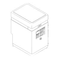
The recommended procedure for attaching the operator to the concrete
pad is first to locate and drill the hole for the right rear redhead.
Review Figure 6, Page 6. After placing the redhead in the hole, remove
the cover and lower the operator over the redhead. Make sure the two
rear mounting holes on the operator are exactly the same distance from
the gate. (Improper alignment of the operator will cause premature
chain and idler sprocket failure.) With the operator properly aligned
with the gate, drill the remaining three holes with the operator in place.
Before inserting the remaining redhead bolts, make sure the operator is
sitting level. If any corners of the operator are resting above the pad,
slide flat washers under the operator and insert the redhead through the
washers. Place the flat washers, lock washers and nuts on the redhead
bolts and tighten down the operator securely.
ELECTRICAL HOOKUP
The operator requires a 3-wire, 115 VAC electrical hook-up for proper
operation. Ideally, the conduit containing the hook-up wires should exit
the concrete pad under the operator. There is a 3" gap in the front of
the bottom plate of the operator provided for this purpose. Run flexible
conduit from the point where the conduit exits the pad and attach it to
the bottom of the right junction box at the front of the frame. Review
Figure 6, Page 6.
If the hook-up exits the pad external to the operator, there's a 7/8"
diameter hole in each side of the frame near the front of the operator.
Connect the conduit to either hole and cut a small slot in the 1-1/2" high
skirt around the base of the cover. This will allow the cover to fit down
flush with the conduit in place. Review Figure 7, Page 7.
Remove the right junction box face plate. Using the wire nuts
provided, attach the three lead wires to the electrical hook-up wires in
the following manner:
1. The BLACK wire attaches to the 115 VAC HOT wire.
2. The WHITE wire to the 115 VAC NEUTRAL wire.
3. The GREEN wire to the GROUND wire.
NOTE: The LP1000 control board comes equipped with a built-in surge
protection which MAY prevent damage to the controller board in the
event of a nearby lightning strike or a surge in the power lines. For the
surge protector to function, and as a general precaution, the operator
must be properly grounded. The third wire for the ground must be
installed .
W A R N I N G !
RISK OF ELECTROCUTION
DO NOT BEGIN THE ELECTRICAL CONNECTION
PROCEDURES UNTIL THE POWER IS TURNED OFF
AT THE CIRCUIT BREAKER
C: INSTALLING THE OPERATOR