Club Car & E-Z-GO
Wiring Diagrams
Not all controllers use the A2 terminal. If not, bolt
the two wires together, insulate with tape or heat
shrink, then secure in safe location.
ControllerPRO
ControllerPRO is free user friendly software for cus-
tomizing your Alltrax AXE Controllers. Download
your copy of ControllerPRO from :
www.alltraxinc.com
Configuration
WARNING: Disconnect all battery charging
sources while programming your AXE controller.
The controllers RS-232 serial port is referenced to
the B- battery connection. Beware of any possi-
ble ground loop faults between your com-
puter and the controller which could damage
both the AXE Controller and PC, or cause per-
sonal injury.
Hardware: Use a STRAIGHT-THROUGH DB-9 pin /
RS-232 serial interface cable to connect the control-
ler to the PC. Alternatively use the preferred DB-9
pin RS-232 serial port to USB adapter.
The AXE controller must be powered before the
ControllerPRO program will have any effect. Before
programming the AXE, READ THE SAFETY
NOTES BELOW. For bench programming prior to
installation, a fused 18V or higher battery may be
used to power the controller. Connect battery nega-
tive to the B- bus bar, battery positive to pin 1.
If you see an error “Motor Controller is Not
Responding”, verify the controller is powered up
and the connections are inserted correctly. If the
error message continues, uninstall then reinstall the
drivers for the communications cable. If the prob-
lem persists, contact Alltrax Technical Support.
Safety Notes:
Alltrax recommends that all motor controller
applications have a fuse in the battery circuit.
Many vehicles do not have a fuse, and will
need to have one installed. The following fuses
manufactured by Bussman or Littelfuse are
acceptable: For controllers rated at 400 amps
or less use ANN250. On controllers rated at
450 amps or more use ANN400. [See:
Doc100-016-A_OP-Fuse-Install-Guide.doc]
Alltrax also recommends a diode across the coil
of the solenoid if it is not already installed. A
minimum of a 100V 1A diode (a 1N4004 is suit-
able) is required. See complete wiring diagrams
for orientation.
Working on electric vehicles, sudden unex-
pected events can occur, it’s recommended to:
• Place the drive axle on jack stands—
wheels off the floor
• When working on wiring or batteries, al-
ways remove rings and watches
• Use the proper safety equipment, eye pro-
tection, and insulated tools
• Never connect a computer while the vehi-
cle is being charged
• Disconnect batteries before installing or
working on the controller
For complete instructions and wiring
diagrams for other configurations and
vehicles, please download our AXE
Manual from www.alltraxinc.com
Alltrax, Inc.
1111 Cheney Creek Rd
Grants Pass, OR. 97527
Phone: 541-476-3565
Fax: 541-476-3566
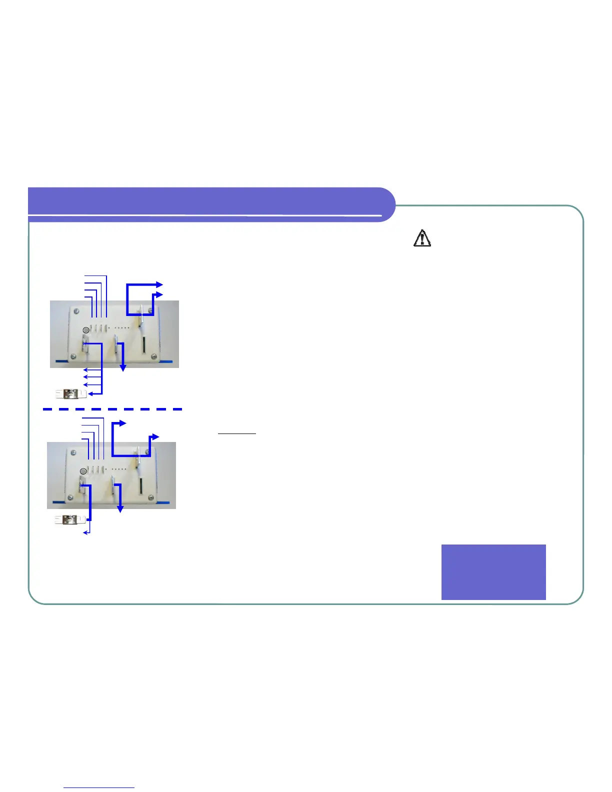
1 2 3 4
RED
GRN
YEL
NOT USED
B-
M-
B+
YELLOW
GREEN
BLUE
PUR
RED/WHT
BLK
1 2 3 4
RED
BLK
WHT
ORG
M-
A2
A2
Optional
B+
Motor A1 (1204/1205 Replacement)
Switch “A” (1206 Replacement)
BATTERY +
* F-N-R Terminal “C” (1204/1205 Replacement)
* Motor A1 (1206 Replacement)
B-
BATT
(-)
BLK
SOLENOID BLK
FUSE
BATT
(-)
BLK
FUSE
LED
LED
QUICK INSTALLATION GUIDE
KEY SWITCH
THROTTLE
THROTTLE
KEY SWITCH
THROTTLE
THROTTLE
1/2 SPD RVRS
 Loading...