Do you have a question about the Alltrax AC1 and is the answer not in the manual?
Essential safety precautions for working on electric vehicles and the Alltrax controller.
Defines the intended use of Alltrax AC controllers and warranty limitations.
Details electrical and physical specifications including model, voltage, temperature, and torque.
Explanation of technical terms and acronyms used in the manual.
Explains the controller's feature to prevent battery damage from low voltage.
Information on the importance and sizing of heavy gauge wires.
Details the required heavy-duty solenoid rating for AC1 controllers.
Explains fuse installation locations and provides a table for controller amperage to fuse rating.
Guidance on proper wire sizing, routing, and connections for performance and safety.
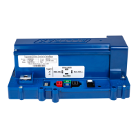
Describes the function of high current terminals like B+, B-, R, U, V, W.
Details the lug assembly and bolts used for high current terminals.
Recommendations for routing and protecting signal wires.
Information on the two-wire temperature sensor and its connection.
Explains the speed sensor, its quadrature signal, and its requirement for AC applications.
Guidance on harness routing and details on encoder pulses and max speed constraints.
Instructs E-Z-GO DCS owners to replace the factory harness for AC1 conversion.
Details the TE_Superseal 4P (C3) and 2P (C2) connectors for speed and temp sensors.
Describes the JST-JWPF O8 connector (C1) for speed and temp sensor harness.
Provides detailed pinout information for C1, C2, and C3 connectors.
Illustrates the female side, top-down view of the 16-pin Molex connector for TXT48.
Lists pin numbers, names, and descriptions for the 16-pin TXT48 Molex connector.
Shows the PDS Molex connectors (Flat 4-pin, Square 4-pin, Rectangle 10-pin).
Provides pinout information for PDS C1, C3, and C4 connectors.
Diagram showing the top view of the controller with dimensions.
Diagram illustrating the side view of the controller with dimensions.
Diagram showing the front view of the controller with dimensions.
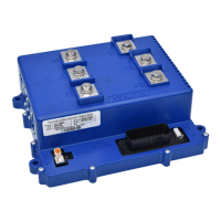
Overview of the AC1 controller for TXT48 conversion with B+, B-, U, V, W connections.
Overview of the AC1 controller for PDS conversion with B+, B-, U, V, W connections.
Information on downloading and using the Alltrax Toolkit software for customization.
Lists blink codes corresponding to different throttle types.
Lists blink codes corresponding to different brake types.
Describes normal operating indicators like solid green, red, or yellow lights.
Details error codes indicated by sequences of green and red LED flashes.
Provides detailed explanations for various error codes, including circuit faults and voltage issues.
Continues explanations for error codes like relay coil overcurrent and horn overcurrent.
Outlines the 2-year warranty, exclusions, and procedures for warranty service.
States limitations on implied warranties and liability for damages.
| Input Voltage | 12-48V |
|---|---|
| Voltage | 12-48V |
| Type | AC Motor Controller |
| Operating Frequency | 16 kHz |
| Throttle Type | 0-5V |
| Operating Temperature | 50°C |
| Protection | Overcurrent, Overvoltage, Undervoltage, Overtemperature |