NCX Wiring Diagrams
QUICK INSTALLATION GUIDE
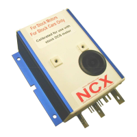
NCX Series
Non-Programmable Motor
Controllers
Our NCX DC Shunt motor controllers are de-
signed to be stock replacement controllers for
stock cars with stock motors only. With a peak
current rating they are not designed for lifted
or high performance vehicles.
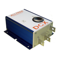
For a high performance controller order our
DCX motor controllers. NCX controllers are not
programmable and must be ordered for the
exact car you are installing them in.
(DCS or PDS only)
Safety Notes:
Alltrax recommends that all motor controller
applications have a fuse in the battery circuit.
Many vehicles do not have a fuse, and will
need to have one installed. The following fuses
manufactured by Bussman or Littelfuse are
acceptable: For controllers rated at 400 amps
or less use ANN250. On controllers rated at
450 amps or more use ANN400. [See:
Doc100-016-A_OP-Fuse-Install-Guide.doc]
Alltrax also recommends a diode across the coil
of the solenoid if it is not already installed. A
minimum of a 100V 1A diode (a 1N4004 is suit-
able) is required. See complete wiring diagrams
for orientation.
Working on electric vehicles, sudden unex-
pected events can occur, it’s recommended to:
• Place the drive axle on jack stands—
wheels off the floor
• When working on wiring or batteries, al-
ways remove rings and watches
• Use the proper safety equipment, eye pro-
tection, and insulated tools
• Disconnect batteries before installing or
working on the controller
DCS Models
Uses standard 9 pin wire harness:
Plug the stock wire harness onto the pins on the
front of the controller.
PDS Models
Uses our PDXA harness (included):
Connect the 10 pin and two 4 pin connectors to
the matching connectors on the stock wire har-
ness.
Note: The 4 pin connector from the motor is not
used in this application.
Alltrax, Inc.
1111 Cheney Creek Rd
Grants Pass, OR. 97527
Phone: 541-476-3565
Fax: 541-476-3566
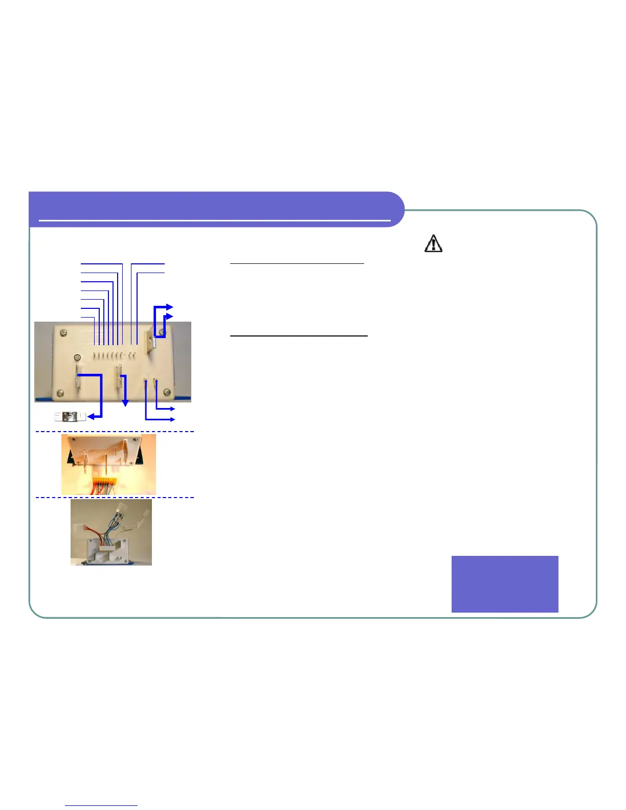
1 2 3 4
M-
B+
MOTOR A2
BATTERY +
MOTOR A1
B-
BATT
(-)
BLK
FUSE
1-THROT-1
2-THROT-2
3-HORN
4-REVERSE
5-FOOT SW
6-KEY SW
7-SOL COIL
10-B+ PWR
9-LOGIC B+
5 6
7 9 10
MOTOR S1
MOTOR S2
LED
F1 F2
For complete instructions and wiring dia-
grams for other configurations and vehicles
please download our DCX Operators Man-
ual from www.alltraxinc.com
PDS
DCS
 Loading...