Do you have a question about the Alma SECURITERRE 640 and is the answer not in the manual?
The GU 7113 EN A SECURITERRE 640 is a grounding system designed for loading gantry applications, ensuring safety during the transfer of flammable liquids or powders. It offers improved safety by detecting reliable grounding, which is essential for preventing static electricity buildup during loading and unloading operations. This device is suitable for use in various loading facilities handling flammable non-conducting liquids and powders, and it can be configured for different modes of operation, including truck, train, and barrel loading.
The Securiterre 640's primary function is to establish and verify a secure earth connection between the loading gantry and the vehicle (truck, train, or barrel) before and during the transfer of hazardous materials. This prevents the accumulation of static electricity, which could lead to sparks and potential explosions in flammable environments. The system uses a clamp to connect to the earth point of the vehicle. Once connected, the device performs a calibration process and monitors the grounding conditions.
The device features LED indicators that provide clear visual feedback on its operational status. These indicators guide the user through the connection and loading process, ensuring that safe conditions are met.
The Securiterre 640 is designed for ease of use with a clear operational procedure:
The procedure for train applications is similar to trucks. Connect the earth clamp to the earth point of the train. The LED indication should transition from yellow to green, confirming a safe situation. If red LEDs remain activated, check the clamp for good connection. After loading, disconnect secondary connections and then the earth clamp, returning it to the clamp holder.
For barrel applications, connect the earth clamp to the earth point of the barrel. The LED indication should change from yellow to green, indicating a safe situation. If red LEDs remain active, check the clamp for good connection. After loading, disconnect secondary connections and then the earth clamp, returning it to the clamp holder.
Magnetic Override: The manual mentions a "Magnetic override" feature, but details are not provided in the excerpt. This likely refers to a mechanism for bypassing certain safety interlocks under specific conditions, possibly for maintenance or emergency, but it should be used with caution and according to strict safety protocols.
The device is designed for robust operation in industrial environments. Regular checks of the earth connection are crucial to ensure proper functioning. The manual emphasizes that the earth connection point should be clean and free from corrosion to achieve correct grounding conditions. If red LEDs remain on after connection, it indicates a potential issue with the earth connection.
The "Return point" is a brass pin on the clamp holder, specifically intended for calibrating the clamp. Users should always place the clamp on this pin when it is not connected to a truck, train, or barrel.
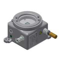
The device is designed to meet stringent safety requirements for working in hazardous areas, as indicated by its ATEX certification. The robust aluminum enclosure and silicone gasket provide protection against environmental factors and ensure durability. The cable glands are designed for secure cable entry, maintaining the integrity of the explosion-proof enclosure. The overall design emphasizes safety, reliability, and ease of integration into existing loading infrastructures.
| Brand | Alma |
|---|---|
| Model | SECURITERRE 640 |
| Category | Measuring Instruments |
| Language | English |