21
0170009-J0 Rev B
5. Operation
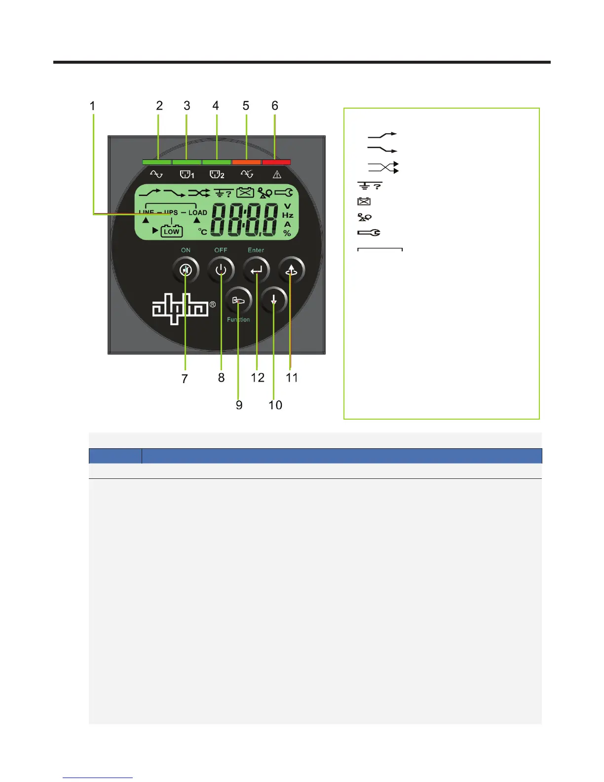
5.1 Front Panel LCD
Table C — LCD Panel Description
Item
Description
1 LCD display
2 Green Utility LED illuminates to indicate that the Utility input voltage is within the range
80Vac~144Vac, or 160Vac~288Vac; the LED ashes to indicate that the Utility input
voltage is within the range 60Vac~79Vac, or 120Vac~159Vac.
3, 4 Green LEDs for Programmable Outlet 1 and Programmable Outlet 2 illuminate to
indicate power is available at the outlets.
5 Amber LED illuminates to indicate the Bypass input is normal.
6 Red Fault LED
7 ON/Alarm silence button
8 OFF button
9 Special functions log in/out
10 SCROLL DOWN key: Go to next page
11 SCROLL UP key, Go to previous page or change the setting of the UPS
12 Enter key: to conrm the change of a UPS setting
Manual
Bypass
Press and hold the ON key (7) and the SCROLL UP key (11) simultaneously for
~3 seconds to transfer from Inverter to Bypass ( the amber Bypass LED blinks
continuously and the buzzer beeps intermittently)
OR
from Bypass to Inverter, when the UPS is on Line Mode and the Bypass Voltage
Window is Normal.
Symbols
Utility Low
Utility High
Line
Site Wiring/ Ground Fault
Battery Abnormal
UPS Overload
UPS in Service Mode
Bypass
LINE/
LOAD
Utility or Bypass Source
Er** Error Codes (see Section
6.3)
OFF UPS Shutoff
FAIL UPS Abnormal Lock
Figure 1 — Front Panel LCD