25
Complete pump
1. Remove the pump head as described above.
2. Unscrew the automatic air vent from the pump outlet.
3. Disconnect the pump unions and withdraw the pump body.
4. Connect the wiring as described above, ensure that pump is set to maximum and re-assemble using new sealing washers.
5. Refill and pressurise the system. (Refer to Commissioning, section 5.1).
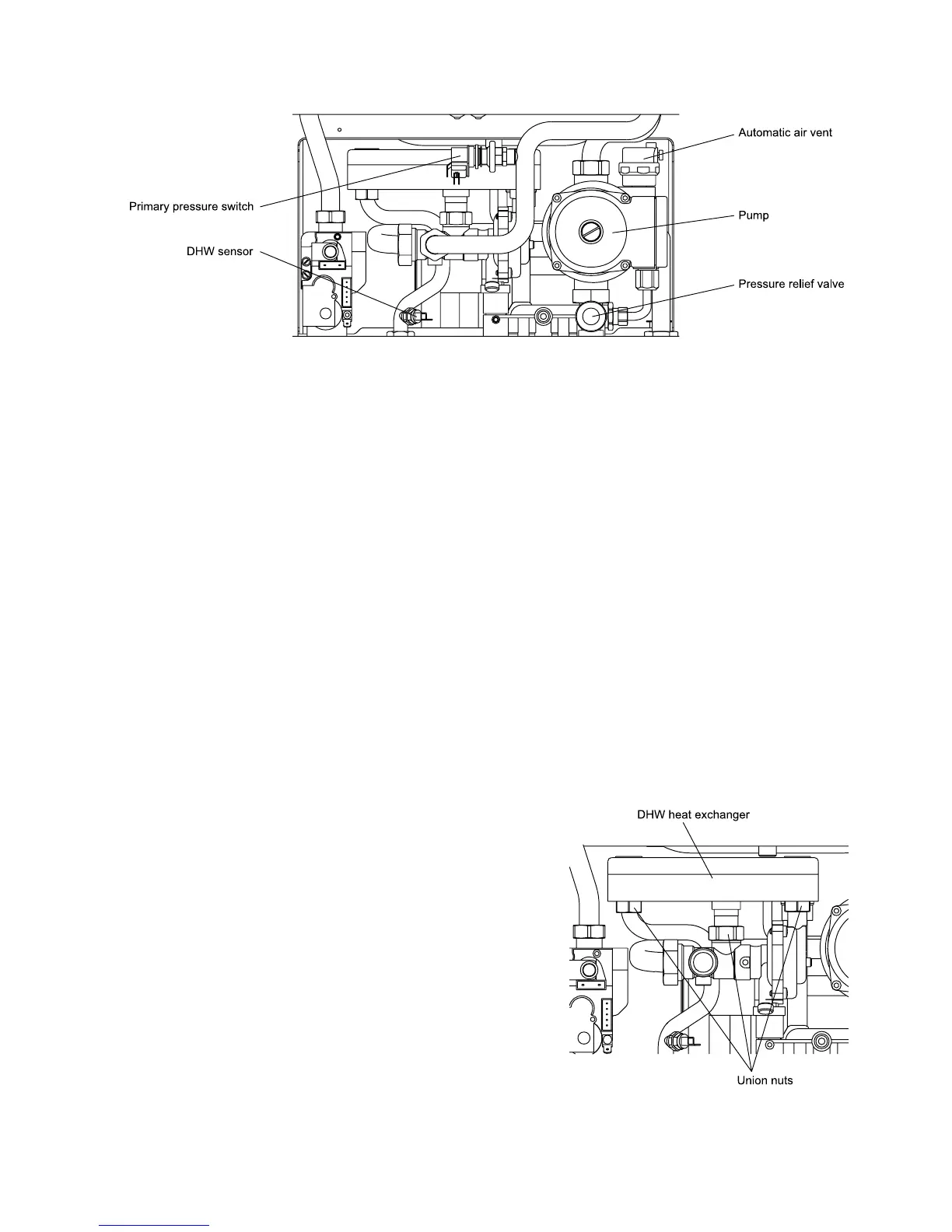
8.22 PRIMARY PRESSURE SWITCH - Fig. 25
1. Gain access behind the casing and drain the boiler heating circuit as described in sections 8.1 and 8.2.
2. Disconnect the wiring from the pressure switch.
3. Unscrew the switch from the primary flow pipe.
4. Using the new washer supplied, re-assemble in reverse order.
When connecting the wiring to the new switch the polarity of the wires is not important.
8.23 PRESSURE RELIEF VALVE - Fig. 25
1. Gain access behind the casing and drain the boiler heating circuit as described in sections 8.1 and 8.2.
2. Remove the four screws securing the bottom tray and remove the tray. Disconnect the pressure relief valve outlet fitting.
3. Release the screw retaining the pressure relief valve and pull out the valve.
4. Re-assemble in reverse order.
5. Refill and pressurise the system. (Refer to Commissioning, section 5.1).
8.24 DHW HEAT EXCHANGER - Refer to Fig. 26
1. Gain access behind the casing and drain the boiler heating and hot
water circuits as described in sections 8.1 and 8.2.
2. Disconnect the three union nuts to the heat exchanger and remove
heat exchanger by lifting it upwards from the rear right hand side 'O'
ring seal connection.
Note: Be careful not to allow water to drip onto any electrical
components.
3. Using the new washers supplied, re-assemble in reverse order.
4. Refill and pressurise the system. (Refer to Commissioning, section
5.1).
Alpha CB24/28 - Component Replacement
Fig. 25
Fig. 26