26
Fig. 27
8.25 MAINS WATER INLET FILTER - Fig. 11
1. Drain the boiler hot water circuit as described in section 8.2. Remove the four screws securing the bottom tray and remove
the tray.
2. Withdraw the filter after disconnecting the unions between the inlet valve and boiler for the CB24X/28X boiler (item H in
Fig. 11) or the union from the inlet of the seasonality valve on the CB24/28.
3. Clean or replace and re-assemble in reverse order.
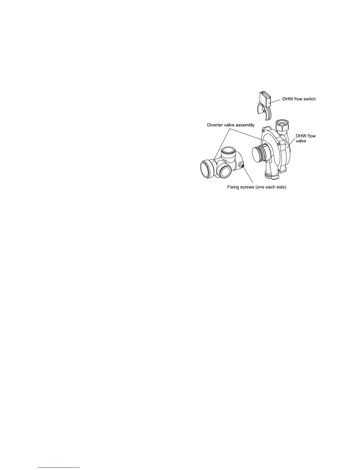
8.26 DIVERTER VALVE ASSEMBLY - Figs. 23 and 27
1. Gain access behind the casing and drain the boiler heating
and hot water circuits as described in sections 8.1 and 8.2.
2. Remove the domestic hot water heat exchanger and flow
switch assemblies from the diverter valve as described in
sections 8.22 and 8.14.
3. Disconnect the union connections from the diverter valve.
4. Release the screws shown in Fig. 23 and raise the valve
slightly to disengage it from the manifold, then lift it out of the
boiler.
5. Re-assemble in reverse order using the new seals supplied.
6. Refill and pressurise the system. (Refer to Commissioning,
section 5.1).
8.27 DHW FLOW VALVE - Fig. 27
1. Remove the diverter valve as described in section 8.26.
2. Unscrew (not necessary to remove) the two screws securing the DHW flow valve to the diverter valve and withdraw the valve.
3. When re-assembling, push the new valve into position, holding it in, while tightening the fixing screws.
4. Re-assemble in reverse order.
8.28 EXPANSION VESSEL
Note: If there is less than 450 mm clearance above the boiler or a rear exit flue is used, it is not possible to replace the vessel,
in which case an additional vessel should be fitted external to the boiler in the central heating return pipe, as close to the boiler
as possible (see Fig. 5).
1. Gain access behind the casing and drain the boiler heating circuit as described in sections 8.1 and 8.2.
2. Disconnect the pipe from the pump inlet manifold and expansion vessel.
3. Remove the four screws securing the top support plate.
4. Lift the expansion vessel out of the boiler.
5. When replacing the vessel, ensure that the connection is towards the front of the boiler and re-assemble in reverse order
using new seals as necessary.
6. Refill and pressurise the system. (Refer to Commissioning, section 5.1).
8.29 SEASONALITY VALVE (N/A to CB24X/28X) - Fig. 11
1. Drain the boiler hot water circuit as described in section 8.2. Remove the four screws securing the bottom tray and remove
the tray.
2. Remove the valve by disconnecting the unions from the bottom of the boiler, the mains inlet valve and filling loop.
3. Re-assemble in reverse order using a new valve.
8.30 CYCLONE (N/A to CB24X/28X) - Fig. 11
1. Gain access behind the casing and drain the boiler heating circuit as described in sections 8.1 and 8.2.
2. Disconnect the unions from the cyclone and re-assemble with a new cyclone.
3. Pressurise the system. (Refer to Commissioning, section 5.1).
Alpha CB24/28 - Component Replacement