15
Cyclone
G
E
F
Condensate
trap
23
70 212.5 70 50
47.5
BDCA
Heating return
valve
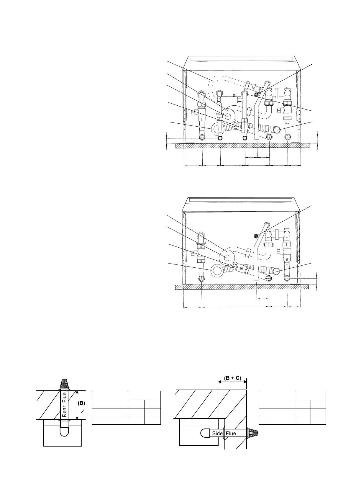
4.6 FIT THE FLUE - Figs. 14, 15
The following procedure applies to fitting an Alpha CD Easy-Flue to both rear or side exit flue - horizontally only.
1. The CD Easy-Flues are suitable for use in the flue length ranges shown in the tables below.
Note: Where the length is less than the minimum or more than the maximum, refer to section 4.7.
Alpha CD24/32 - Installation
Fig. 13
A - Heating flow (22 mm)
B - Hot water outlet (15 mm)
C - Gas inlet (22 mm)
D - Cold water mains inlet (15 mm)
E - Heating return (22 mm)
F - Pressure relief valve (15 mm)
G- Heating drain point
H - Cold water inlet filter
I - Condensate discharge pipe
J - Cyclone drain point
Note: Disconnect the filling loop after
filling the central heating system.
Alpha CD24C and CD32C
Alpha CD24S
A - Heating flow (22 mm)
B - Gas inlet (22 mm)
C - Heating return (22 mm)
D - Pressure relief valve (15 mm)
E - Heating drain point
F - Condensate discharge pipe
G - Cyclone drain point
Fig. 14 Fig. 15
CD Easy-Flue
500 mm
1000 mm
B (mm)
Max
520
915
Min
280
675
CD Easy-Flue
500 mm
1000 mm
Max
460
855
Min
220
615
B + C (mm)
Heating return
valve
Filling loop
Cyclone
J
G
H
I
Condensate
trap
20
23
70
70
95 95 70 50
47.5 47.5
CB DFEA