5
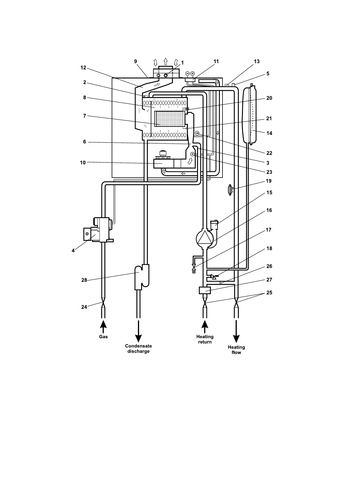
2.10 CD24S BOILER SCHEMATIC
Alpha CD24/32 - Technical Data
1 - Flue sampling point
2 - Flue thermostat
3 - Injector
4 - Gas valve
5 - Primary temperature sensor
6 - Venturi
7 - Main burner
8 - Primary/condensing heat exchanger
9 - Room sealed chamber
10 - Fan
11 - Pressure differential test points
Fig. 2A
12 - Flue hood
13 - Overheat thermostat
14 - Expansion vessel
15 - Automatic air vent
16 - Pump
17 - Drain point
18 - Pressure relief valve
19 - Primary pressure switch
20 - Ignition electrodes
21 - Flame sensing electrode
22 - Venturi negative point
23 - Venturi positive point
24 - Gas service cock
25 - On/off valve (2 off)
26 - Automatic by-pass
27 - Cyclone separator
28 - Condensate trap