4
DOOR RELEASE DIAGRAMS - continued
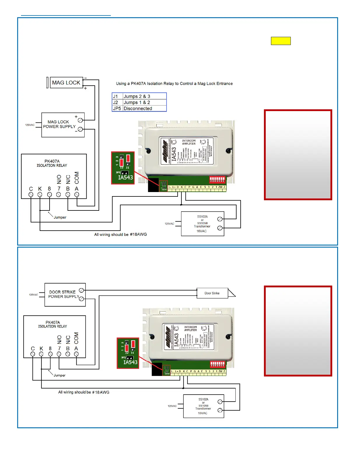
Set jumpers as shown in the chart below. This configuration is used when a magnetic door lock has its own
dedicated power supply. The PK407A only provides a dry contact which in this Normally Closed mode, allows
voltage to flow to a magnetic lock through the B & A terminals. When the inside station DOOR Button is
pressed, the relay opens the circuit, disconnecting the power and releases the door. Insure that proper polarity
between the magnetic lock and its power supply is observed.
The length of door release time is determined by the dipswitch settings (approx. 2, 10, or 25 seconds).
USING THE
PK407A
ISOLATION
RELAY
for a
MAG LOCK
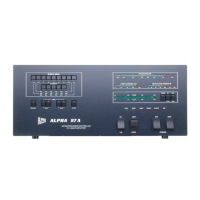
To use the PK407A as an isolation relay for a door strike with a separate power supply, the wiring and
umper settings are the same as above, except the wire going to the B terminal (Normally Closed) would go
to the A terminal (Normally Open) instead. This way power from the IA543 would close the connection to
apply power to the door strike and release the door.
USING THE
PK407A
ISOLATION
RELAY
for a
DOOR
STRIKE