EasyManua.ls Logo

AlpicAir AWI-26HPR1 - User Manual

Default Icon
32 pages
Print Icon
To Next Page IconTo Next Page
Loading...
Cover
SERVICE MANUAL
AWI/AWO-20HPR1 Gamma
AWI/AWO-26HPR1 Gamma
AWI/AWO-35HPR1 Gamma
AWI/AWO-54HPR1 Gamma
AWI/AWO-71HPR1 Gamma
Question and Answer IconNeed help?

Do you have a question about the AlpicAir AWI-26HPR1 and is the answer not in the manual?

Summary

1. Precaution

1.1 Safety Precaution

Essential safety instructions to prevent injury and damage.

1.2 Warning

Critical warnings related to installation and operation.

2. Function

Indoor unit

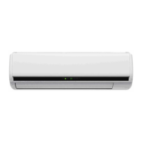
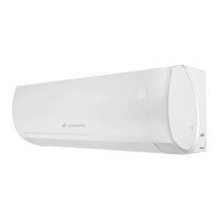
Functions and operations specific to the indoor unit.

Outdoor unit

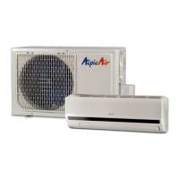
Functions and operations specific to the outdoor unit.

3. Dimension

3.1 Indoor unit

Physical dimensions and specifications of the indoor unit.

3.2 Outdoor unit

Physical dimensions and specifications of the outdoor unit.

4. Refrigerant cycle diagram

Heat pump mode

Diagram illustrating the refrigerant flow in heat pump mode.

5. Operation limits

5.1 Cooling operation

Operating temperature ranges for cooling mode.

5.2 Heating operation

Operating temperature ranges for heating mode.

6. Wiring diagram

7. Installation details

7.1 Wrench torque sheet for installation

Specifies torque values for installation fittings.

7.2 Connecting the cables

Guidelines for selecting power cord specifications.

7.3 Pipe length and the elevation

Details on pipe sizing, length, and elevation limits.

7.4 Air purging of the piping and indoor unit

7.5 Pumping down (Re-installation)

7.6 Re-air purging (Re-installation)

7.7 Balance refrigerant of the 2-way, 3-way valves

7.8 Evacuation

7.9 Gas charging

8. Electronic function

8.1 Proper symbols and their meaning

Definitions of technical symbols and abbreviations used.

8.2 Function

Overview of various operational modes and features.

8.3 Protection

Details on safety protections and error conditions.

8.4 Fan-only mode

8.5 Cooling mode

8.6 Dehumidifying mode

8.6.1 The 4-way valve is off in dehumidifying mode

Valve status during dehumidifying operation.

8.6.2 Compressor and Indoor Fan actions in dehumidifying mode

Compressor and fan behavior in dehumidifying mode.

8.6.3 Low room temperature protection

Protection triggered by low room temperatures.

8.6.4 Anti-freezing function

Anti-freezing mechanism in dehumidifying mode.

8.6.5 Fan actions in dehumidifying mode

Indoor fan behavior in dehumidifying mode.

8.7 Heating mode

8.7.1 4-way valve operation

4-way valve behavior in heating and defrosting modes.

8.7.2 Outdoor fan operation

Outdoor fan control in heating and defrosting.

8.7.3 Compressor and fan motor actions

Compressor and fan motor control during heating.

8.7.4 Indoor Fan actions at heating mode

8.7.5 Auto wind at heating mode

8.7.6 Indoor evaporator high-temperature protection

8.7.7 Louver opens to Standard Angle ANGLHEAT

8.8 Defrosting mode (available for heating mode)

8.8.1 Defrosting condition

Criteria for initiating the defrost cycle.

8.8.2 Defrosting time

Duration of the defrost cycle.

8.8.3 Ending condition of defrosting

Conditions for ending the defrost cycle.

8.8.4 Defrosting Actions

Actions taken during the defrost mode.

8.9 Auto mode

8.9.1 Mode selection

Automatic selection of operating modes based on temperature.

8.9.2 Indoor fan behavior

Automatic fan operation based on selected mode.

8.9.3 Indoor fan blade motion

Fan blade movement according to selected mode.

8.9.4 Mode duration

Minimum operating time for selected modes.

8.10 Force cooling function

8.10.1 Select function

How to activate the forced cooling function.

8.10.2 Operation details

Specific operation of forced cooling and DRY mode.

8.10.3 Protections

Protections applicable to forced cooling operation.

8.10.4 Forced Auto function

Activating and operating the forced auto function.

8.11 Sleep mode

8.11.1 Availability

Modes where sleep function is available.

8.11.2 Cooling

Sleep mode operation in cooling mode.

8.11.3 Heating

Sleep mode operation in heating mode.

8.11.4 Auto

Sleep mode operation in auto mode.

8.12 Auto restart function

8.13 Turbo mode

9. Model and Parameters

10. Troubleshooting

10.1 Display board

Explanation of indicator lights on the display.

10.2 Troubleshooting

Table of failure phenomena and their corresponding indicators.

10.3 Diagnostic chart

Flowchart for diagnosing operational issues.

10.4 Resetting phenomenon often occurs during operation.

10.5 Operation lamp flashes and Timer lamp off.

10.6 Operation lamp flashes and Timer lamp on.

10.7 Operation lamp off and Timer lamp flashes

10.8 Operation lamp on and Timer lamp flashes

10.9 Operation lamp flashes, Timer lamp flashes.

11. Characteristic of temperature sensor

AlpicAir AWI-26HPR1 Specifications

General IconGeneral
BrandAlpicAir
ModelAWI-26HPR1
CategoryAir Conditioner
LanguageEnglish

Related product manuals