This document is a service manual for the Alpine 3321 11-Band Graphic Equalizer. It provides comprehensive information for understanding, operating, and maintaining the device.
Function Description:
The Alpine 3321 is an 11-band graphic equalizer designed to allow users precise control over the frequency response of their audio system. It features eleven adjustable frequency bands, enabling fine-tuning of sound characteristics to suit personal preferences or compensate for acoustic imperfections in a vehicle's interior. The device also incorporates a fader control, input level display, and a subwoofer section with adjustable frequency, output level, and phase control. A defeat switch allows bypassing the equalization for comparison. The unit includes RCA input and output connectors for integration into an audio system, along with leads for battery, ground, and remote-on connections.
Important Technical Specifications:
- Power Supply: DC 14.4V (operating range 11V to 16V).
- Total Harmonic Distortion: 0.04%.
- Input Sensitivity/Impedance: 0.5 ± 200mV / 9kohm.
- Output Impedance: 1 kohm.
- Frequency Response: 30 Hz to 40 kHz.
- Channel Crosstalk Attenuation: 64 dB.
- Frequency Shaping Equalizer Controls:
- Boost: 12 + 3dB, 12 - 6dB.
- Cut: -12 + 3dB, -12 - 6dB.
- Equalization Frequencies: 31.5 Hz, 63 Hz, 125 Hz, 190 Hz, 250 Hz, 500 Hz, 1 kHz, 2.2 kHz, 4.5 kHz, 9 kHz, 18 kHz.
- Subwoofer Frequency Response: 50, 80, 120 ± 20 Hz.
- Subwoofer Control Effect: 15 ± 3dB.
- Signal to Noise Ratio (IHF-A): 94 dB.
- Current Drain: 300 mA.
- Fader Control Effect: 40 dB.
- Channel Unbalance: 0 ± 3dB.
- Semiconductors: 19 ICs, 31 Transistors, 13 Diodes, 5 Zener Diodes, 20 LEDs.
- Dimensions:
- Nose: 178(W) × 25(H) × 16(D)mm.
- Chassis: 178(W) × 25(H) × 115(D)mm.
- Weight: 0.7 kg.
Usage Features:
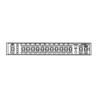
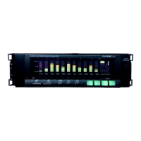
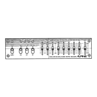
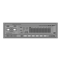
The front panel of the Alpine 3321 provides intuitive controls for audio adjustment:
- FADER Control: Adjusts the balance between front and rear audio channels.
- INPUT LEVEL Display: Visual indicator for monitoring input signal strength.
- 11-Band Graphic Equalizer Controls: Individual sliders for each of the eleven frequency bands (31.5 Hz to 18 kHz) to boost or cut specific frequencies.
- EQUALIZER DEFEAT Switch: Allows the user to bypass the equalizer circuit, providing a direct comparison between the equalized and unequalized sound.
- SUBWOOFER ON/OFF Switch: Activates or deactivates the subwoofer output.
- SUBWOOFER OUTPUT LEVEL Control: Adjusts the volume of the subwoofer output.
- FREQUENCY CROSSOVER SELECTOR: Selects the crossover frequency for the subwoofer output (50 Hz, 80 Hz, or 120 Hz).
- SUBWOOFER PHASE Switch: Adjusts the phase of the subwoofer output (0° or 180°).
- SUBWOOFER STEREO/MONO Switch: Configures the subwoofer output for stereo or mono operation.
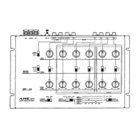
The rear panel features:
- RCA Input Connector (J301): For connecting the audio source.
- Front Output RCA Connector (J302): For connecting to the front amplifier inputs.
- Rear Output RCA Connector (J303): For connecting to the rear amplifier inputs.
- Subwoofer Output RCA Connector (J304): For connecting to a subwoofer amplifier.
- Remote-On Lead (E301-2): For remote power control.
- Ground Lead (E301-3): For system grounding.
- Battery Lead (E301-1): For main power connection.
Maintenance Features:
The service manual provides detailed information crucial for maintenance and repair:
- Parts Locations: Diagrams illustrating the placement of components on the printed circuit boards (P.C.Boards) and within the cabinet. This includes the EQ P.C.Board, Volume P.C.Board, and Control P.C.Board.
- Block Diagram: A high-level overview of the device's electronic architecture, showing the signal flow through various stages like buffer amplifiers, graphic equalizer amplifiers, crossover filters, and line amplifiers.
- Schematic Diagram: Detailed circuit diagrams for each P.C.Board, including component values and interconnections, essential for troubleshooting and component replacement.
- Electrical Parts List: A comprehensive list of all electrical components, including their part numbers, descriptions, and abbreviations (e.g., resistors, capacitors, ICs, transistors, diodes, coils, switches, connectors). This list is vital for ordering replacement parts.
- Exploded View (Cabinet) and Cabinet Assembly Parts List: Diagrams and lists detailing the mechanical components of the device, such as covers, screws, knobs, cushions, and the nosepiece assembly, facilitating disassembly and reassembly.
- Semi-Conductor Lead Identifications: Pinout diagrams for integrated circuits (ICs) and transistors, which are critical for testing and replacing these components correctly.
- Packing Method View and Packing Assembly Parts List: Information on how the product is packaged, useful for understanding how to safely transport or store the unit.
The manual notes that specifications and design are subject to change without notice due to continuous product improvement. It also specifies that carbon resistors under 1½ watts are not listed in the parts list and should be confirmed via the schematic diagram. The parts list also differentiates between components for North American and European models where applicable.