Do you have a question about the Alpine 3672 and is the answer not in the manual?
Detailed electrical and performance parameters of the unit.
Troubleshooting steps for when the remote-on indicator light does not illuminate.
Diagnosing and resolving issues where no sound or limited sound is produced.
Identifying and fixing noise from the alternator in the audio system.
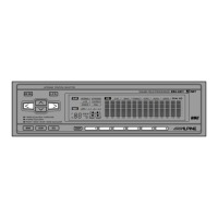
Details on the 6-way signal division and independent outputs for system flexibility.
Information on continuously adjustable crossovers and phase switches for tuning.
Description of the DC-to-DC switching power supply and gold-plated connectors.
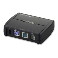
Features like remote-on indicator LED and trunk-mount capability.
Details on connecting power, ground, and remote-on signals, and the function of the fuse.
Explanation of how to connect CH 1/2 and CH 3/4 inputs based on head unit output.
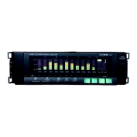
Details on various output connectors and the function of output level controls.
Explanation of mode selector switches and phase switches for tuning.
Settings for subwoofer mode, stereo/mono, and output level adjustments.
Explanation of how crossover networks divide the audio spectrum into different frequency segments.
Details on the 2/1 input selector and subwoofer mode switch functions.
Comparison of passive and active crossover network implementations and their benefits.
Guidance on routing audio cables to minimize noise and connecting head unit outputs to the 3672.
Instructions for setting up CH 1/2 and CH 3/4 outputs in various modes and adjusting levels.
Detailed instructions for connecting power and ground, including important safety precautions.
Prerequisites for making accurate adjustments, including component mounting and environment.
Step-by-step instructions for adjusting the system using an RTA and test signals.
Instructions for adjusting the system by ear without using a Real Time Analyzer.
Visual representation of the internal signal paths and component interconnections.
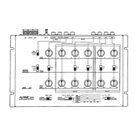
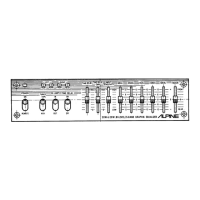
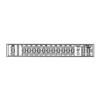
Diagrams showing the physical placement of components on various printed circuit boards.
Layouts for the main PC board, block terminal, and LED PC board.
The complete electrical schematic of the unit's circuitry.
Table listing voltage values for various transistors under specific measurement conditions.
Table listing voltage values for various ICs under specific measurement conditions.
Diagram showing the assembly of the unit's cabinet with numbered parts.
List of parts required for cabinet assembly, with part numbers and descriptions.
List of ICs, transistors, diodes, filters, and switches with their part numbers.
Comprehensive list of capacitors with part numbers, types, and values.
List of resistors with part numbers, values, and wattage, including volume controls.
Parts list for frequency control and RCA out boards, including components.
List of components included in the installation kit and packing materials.
List of owner's manuals included for different regional models.
Pin identification and diagram for the µPC4570HA integrated circuit.
Pin identification and diagram for the M5238L integrated circuit.
Detailed schematic views of specific functional blocks within the unit.
| Heads | 3 (Erase, Record, Playback) |
|---|---|
| Track System | 4-track, 2-channel stereo |
| Inputs | Line |
| Outputs | Line, Headphone |
| Power Supply | AC 60Hz |