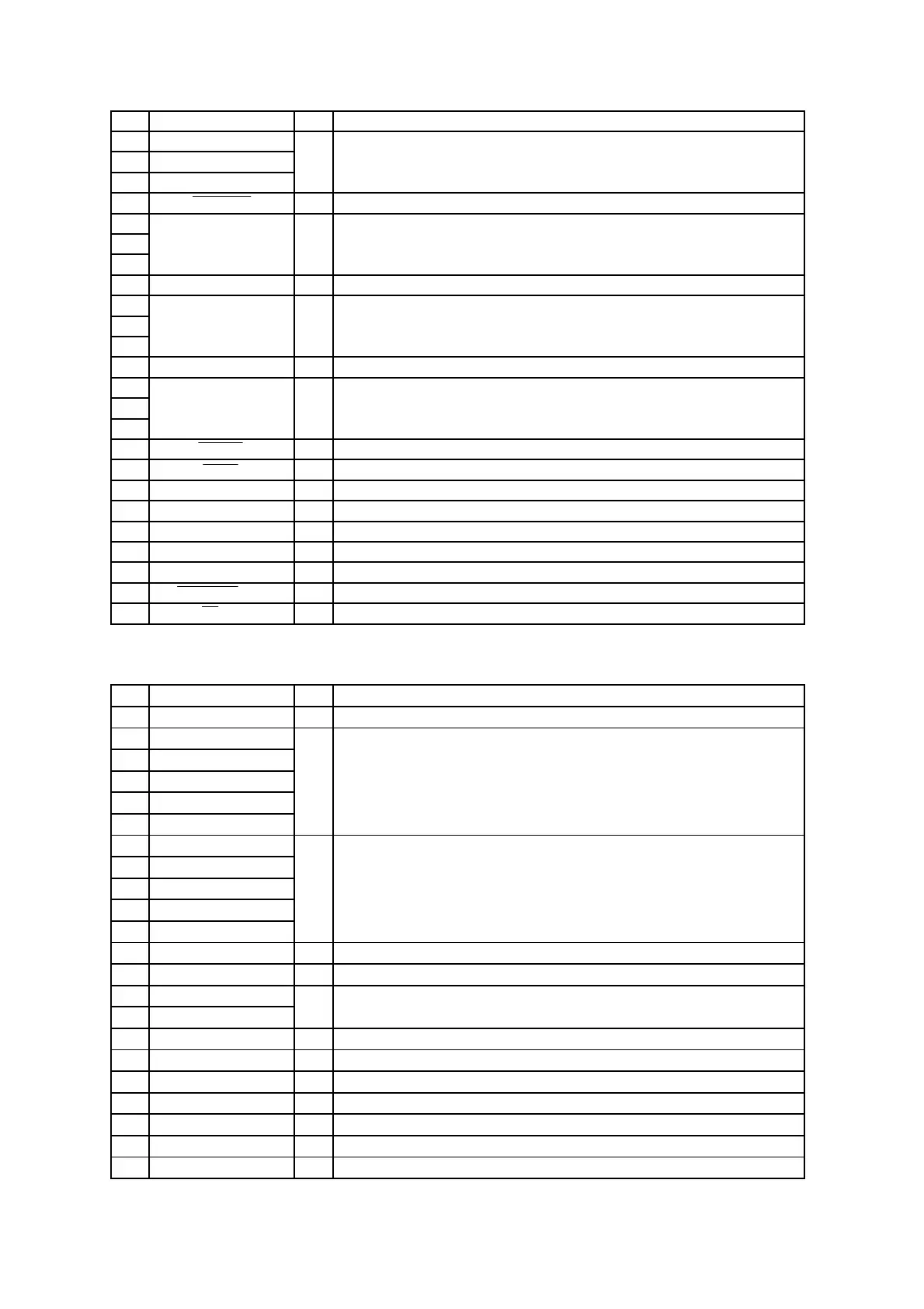
CDA-9833R
No. Symbol I/O Terminal Description
51 MARKET1
52 MARKET2
53 MARKET3
54 AUTOADJ I Auto adjustment start signal terminal of FM/AM TUNER. (L:start)
55
I
71
72 VSS - GND terminal.
73
I
80
81 VDD - Power supply terminal.
82
I
91
92 PAUSE I Audio signal detect terminal. (L:Blank)
93 DAVN I Data available input terminal of RDS Decoder.
94 TEST/VPP - GND terminal.
95 RDS SDA I/O Data input/output terminal to RDS Decoder.
96 RDS SCL O Clock output terminal to RDS Decoder.
97 IIC SCL O I2C clock output terminal to TUNER-IC(TDA7511).
98 IIC SDA I/O I2C data input/output terminal to TUNER-IC(TDA7511).
99 TUNER ON(NC) - No connect terminal.
100 FM/AM O FM/AM power supply switching terminal. (L:FM)
UPD78F9026 : IC401
No. Symbol I/O Terminal Description
1 SEA GRN O Control signal output terminal for SEARCH KEY lighting LED. (GREEN)
2 KI4
3 KI3
4 KI2
5 KI1
6 KI0
7 KS4
8 KS3
9 KS2
10 KS1
11 KS0
12 NC(GND) - GND connect terminal.
13 GND(VPP) - GND terminal.
14 XTAL2
15 XTAL1
16 GND - GND terminal.
17 VDD - Power supply terminal.
18 RESET I System RESET input terminal.
19 2 Lit GREEN O Green LED control signal output terminal for Key lighting.
20 2Lit AMB O Amber LED control signal output terminal for Key lighting.
21 BLACK OUT O LED control signal output terminal for LCD backlight.
22 LCD CLK I Clock output signal input terminal from MAIN u-COM.
I Crystal OSC connect terminal for main system clock OSC. (5MHz)
No connect terminal.
I Key Matrix input terminal.
O Key Matrix output terminal.
I Area set up terminal.
NC - No connect terminal.
NC - No connect terminal.
NC -
 Loading...