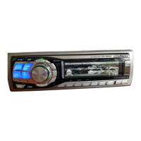
CDA-9833R
No. Symbol I/O Terminal Description
23 F-STBY I Active stand-by output signal input terminal from MAIN u-COM.
24 SEA AMB O Control signal output terminal for SEARCH KEY lighting LED. (AMBER)
25 RED OUT O HIGH output terminal only at RGB LED RED Mode.
26 F-RXD I DATA input signal input terminal from MAIN u-COM.
27 F-TXD O DATA output signal output terminal to MAIN u-COM.
28 F-SCK O Clock signal output terminal to to LCD Driver.
29 LCD DI O Serial DATA output terminal to LCD Driver.
30 LCD AO O Address BUS selection signal output terminal to LCD Driver.
31 LCD CSI O CE signal output terminal to LCD Driver.
32 LCD RESET O RESET signal output terminal to LCD Driver.
33 RGB CLK O Clock signal output terminal to RGB Driver.
34 RGB DATA O Serial DATA output terminal to RGB Driver.
35 RGB CS O CS signal output terminal to RGB Driver.
36 RGB RST O RESET signal output terminal to RGB Driver.
37 GND - GND terminal.
38 VDD - Power supply terminal.
39 GND - GND terminal.
40 AUDIO AMB
41 AUDIO GRN
42 MENU LED O Indicator LED control signal output terminal for MENU Key.
43 MX LED O Indicator LED control signal output terminal for MX Key.
44 DIMMER O Control signal output terminal for backlight LED.
M30626FHPGP : IC501
No. Symbol I/O Terminal Description
1 NC - No connect terminal.
2 REM DATA I Remote control input terminal.
3 F-COM RXD O DATA output signal output terminal to FRONT u-COM.
4 F-COM TXD I DATA input signal input terminal from FRONT u-COM.
5 F-COM SCLK I Clock output signal input terminal from FRONT u-COM.
6 GND
7 GND(CNVss)
8I
9O
10 RESET I System RESET input terminal.
11 6MHz O Crystal OSC connect terminal for main system clock OSC.
12 GND - GND terminal.
13 6MHz I Crystal OSC connect terminal for main system clock OSC.
14 VCC - Power supply terminal.
15 NMI - Pull-up connect terminal.
16 8V-DET I 8V ON detection input terminal.
17 ACC-DET I ACC ON detection signal input terminal.
18 BAT-DET I BATT ON detection signal input terminal.
19 BL-LED O LED control signal output terminal for LCD backlight.
20 V-CONT O CD BATT power supply control signal output terminal.
21 NC - No connect terminal.
22 BUZZER O BUZZER signal output terminal.
O LED control signal output terminal for AUDIO Block.
32.768kHz Crystal OSC connect terminal for sub system clock OSC.
- GND terminal.

 Loading...