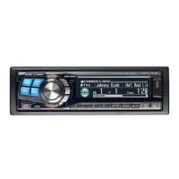
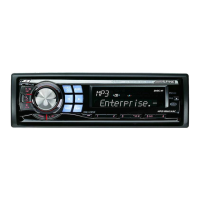
CDA-9833R
No. Symbol I/O Terminal Description
23 BUS-IN I Ai-NET BUS signal input terminal.
24 CD RST O System RESET output terminal to CD u-COM.
25 CD STBY O Active stand-by request signal output terminal to CD u-COM.
26 NC - No connect terminal.
27 BUS IN I Ai-NET BUS signal input terminal.
28 BUS OUT O Ai-NET BUS signal output terminal.
29 RDS TXD O Command DATA signal output terminal to RDS u-COM.
30 RDS RXD I Status DATA signal input terminal from RDS u-COM.
31
32
33 CD TXD O Serial DATA output terminal to CD Mechanism.
34 CD RXD I Serial DATA input terminal from CD Mechanism.
35 CD
CLCK O Serial clock output terminal to CD Mechanism.
36 F-START O Communication start output terminal to FRONT u-COM.
37 F-RESET O RESET signal output terminal to FRONT u-COM.
38
39
40 NOSE PWR O NOSE arround power supply control signal output terminal.
41 NC - No connect terminal.
42 IIC-DATA I/O I2C serial DATA input/output terminal.
43 IIC-CLK O I2C serial clock output terminal.
44 FAN CONT O FAN control output terminal.
45 ENCODER2 I Encoder-2 input terminal.
46 ENCODER1 I Encoder-1 input terminal.
47 IN DIMMER I Outernal DIMMER detection signal input terminal.
48 PWR IC ON O POWER-IC stand-by control signal output terminal.
49 O.REM O REMOTE ON signal output terminal for outernal AMP.
50 NC - No connect terminal.
51 A-MUTE O A-MUTE signal output terminal.
52 IN INT I Outernal interrupt signal input terminal. (at interrupt:H)
53
I
56
57 60W CONT O Power supply ON control output terminal for 60W.
58 ZERO DET I 0 Bit MUTE signal input terminal from CD u-COM.
59 IIC-DATA I/O I2C serial DATA input/output terminal.
60 VCC - Power supply terminal.
61 IIC-CLK O I2C serial clock output terminal.
62 GND - GND terminal.
63 POWER CONT O Power supply control siganal output terminal for AUDIO/lighting.
64 NC - No connect terminal.
65 XRST(DSP) O RESET signal output terminal to DSP-IC.
66 AREA I AREA/Function definition terminal.
67 SCLK(DSP) O Serial clock output terminal to DSP-IC.
68 RVDT(DSP) O Serial DATA output terminal to DSP-IC.
69 TRDT(DSP) I Serial DATA input terminal from DSP-IC.
70 XLAT(DSP) O DATA latch signal output terminal to DSP-IC.
71 RDS FIN I Status DATA signal input terminal from RDS u-COM.
NC - No connect terminal.
NC - No connect terminal.
- No connect terminal.NC
 Loading...