EasyManua.ls Logo

Alpine i209-GM User Manual

Alpine i209-GM
20 pages
To Next Page IconTo Next Page
Page #1 background imageLoading...
Page #1 background image
Chevrolet/GMC
FULL SIZE TRUCK 1/20
CHEVROLET/GMC
i209-GM
Installation Manual
Model: Full Size Truck
Model Year: 2014-2018
(BOSE® Sound System requires KCX-BOSE-GM which is sold separately)
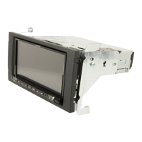
Introduction
Congratulations on purchasing the i209-GM. This installation manual is designed to take you through the
step-by-step installation of the i209-GM into a 2014-2018 Chevrolet Silverado / GMC Sierra. Please familiarize
yourself with the owners manual and if you still have additional questions please call 1-800-TECH-101.
Note
Design and specifications are subject to change without notice for improvement.
To Ensure Safe Use, Always Follow These Precautions
The installation of this product requires specialized skills and experience. We recommend that you have the
product installed by the store that you purchased it from.
Before you use this product, be sure to carefully read this installation manual and the separate user's manual
so that you can use the product correctly. Alpine Electronics bears no responsibility for problems that arise as
a result of failure to follow the instructions in the manuals.
This manual includes a number of symbols that are intended to help you use the product safely, to prevent
harm to you and others, and to protect against damage to property. These symbols and their meanings are
listed below. Make sure you fully understand these symbols before you begin reading the main text.
Explanations of Injury and Damage That May Result from Incorrect Use
Warning
Ignoring the content marked by this indication and using the product incorrectly is
expected to lead to death or serious injury.
Caution
Ignoring the content marked by this indication and using the product incorrectly is only
expected to lead to injury or property damage.
CHEVROLET SILVERADO
Model Year
WT, LS, LT, LT Z71, LTZ, LTZ Z71 2014-2018
GMC SIERRA
SIERRA, SLE, SLT 2014-2018
* The specified vehicles have been tested and have met compatibility specs at the time of testing. Compatibility is
not guaranteed if the manufacturer has made production changes to the listed vehicles above.
Warning: Before you begin wiring, remove the ground wire from the negative
terminal of the battery. Failing to do so could lead to electric shock, injury or
improper product operation.

Questions and Answers:

Alpine i209-GM Specifications

General IconGeneral
BrandAlpine
Modeli209-GM
CategoryCar Video System
LanguageEnglish

Summary

Manual Overview and Warnings

Model and Compatibility Information

Details the compatible vehicle models and years for the i209-GM installation.

Important Safety Precautions

Covers battery disconnection, general warnings, and explanation of safety symbols.

Types of Precautions and Safety Warnings

Forbidden and Mandatory Actions

Defines symbols indicating actions that must not or must be performed.

General Safety Warnings

Covers warnings regarding product modification, small objects, fuses, and power connections.

Vehicle and Component Safety Guidelines

Body Integrity and Airbag Safety

Guidelines to prevent vehicle body damage and avoid airbag interference during installation.

Wiring and Component Handling

Instructions for proper wiring connections, cord management, and ventilation.

Installation Tools and Accessories

Required Tools for Installation

Lists all necessary tools for the i209-GM installation process.

Included Accessory Components

Details the parts and accessories included in the i209-G Source Unit box.

Installation Kit and Maestro Parts

Installation Kit Components

Lists parts included in the G-KTX-i209-GM installation kit.

iDatalink Maestro Module Components

Details the parts associated with the iDatalink Maestro module.

iDatalink Maestro Module Programming

Weblink Software Setup

Steps for installing the Weblink plug-in and registering an account.

Module Programming Steps

Procedure for connecting the module, logging in, and programming the vehicle.

Factory Radio Removal Procedure

Dash Panel and Trim Removal

Instructions for removing dash trim, climate control module, and knee cover.

Component Removal Steps

Guidance on removing the radio tuner, CD player, and steering column covers.

USB Port Integration

USB Port Integration Overview

Explains integration for glove box, dash, and center console USB ports.

Glove Box USB Installation Steps

Procedure for removing glove box compartments and connecting the USB port.

Component Locations and GPS Antenna Installation

Key Component Identification Diagram

Diagram showing the location of key components within the vehicle.

GPS Antenna Installation Steps

Guidance on GPS antenna placement, cable routing, and interference avoidance.

Installation Instructions

Harness and Module Connections

Connecting steering wheel harness, OBDII, main harness, and Maestro module.

Component Installation Steps

Installing the radio tuner and connecting the HVAC controller.

Installation Instructions (Continued)

Display and Bezel Assembly

Connecting the display, climate control, and securing the restyle bezel.

Button Illumination and Vent Attachment

Selecting button illumination color and attaching side vent covers.

Exploded-View Diagram

Visual breakdown of the OEM bezel and climate controller.

i209-GM Wiring Diagram

Main Wiring Connections

Diagram for steering wheel, OBDII, HVAC, and camera connections.

iDatalink Maestro Module Wiring

Wiring diagram detailing connections to the iDatalink Maestro module.

Wiring Diagram Details and External Connections

Display Color and HDMI Selector Wiring

Wiring for button illumination color and optional HDMI selector.

DVD Player and Phone Connectivity Wiring

Connections for optional DVD player and smartphone integration.

Detailed i209-GM Wiring Diagram

Interface and Power Wiring

Wiring for interface cables, power, ACC, battery, and ground connections.

Speaker and Remote Control Wiring

Diagrams for speaker outputs and remote control signal wiring.

Wire Harness Pin Outs

Radio, Display, and AUX Pin Outs

Pin assignment details for radio main, display power, and AUX connectors.

Camera, OBD/SWC, and Audio Pin Outs

Pin assignments for camera, OBD/SWC, and audio input/output harnesses.

GM Harness and Speaker Pin Outs

Pin configurations for GM specific harnesses and speaker connections.

OEM Camera Retention

Camera Connection Methods

Explains camera connection for trucks with HMI box and work trucks.

Camera Activation for Non-Reverse Use

Modifies camera wiring to enable use with the direct camera hard key.

KAC-001 Accessory Control Module Connection

KAC-001 Module Wiring Diagram

Details wiring for the KAC-001 module's power, interface, and output harnesses.

Maestro Module Interface Wiring

Shows the interface connections between the KAC-001 and Maestro module.

External Component Connections

External Amplifier Connection Diagram

Wiring for connecting an external amplifier using RCA and remote leads.

SiriusXM Module Connection

Guidance on connecting the SiriusXM module and antenna.

System Setup and Troubleshooting

Initial i209-GM Setup Guide

Steps for initial setup including ignition, power, language, and parking brake.

Troubleshooting Common Issues

Addresses common problems like instrument cluster data, USB, and phone connectivity.

Troubleshooting Guide (Continued)

Module Programming and Headunit Issues

Resolves issues with serial numbers, module programming, and headunit power.

System Functionality Issues

Troubleshoots settings menu access, voice recognition, and climate control buttons.

Audio, Navigation, and Connectivity Issues

Addresses audio muting, SXM speakers, GPS signal, and phone recognition problems.

Related product manuals