Basic
Connection Diagram for R-A60F
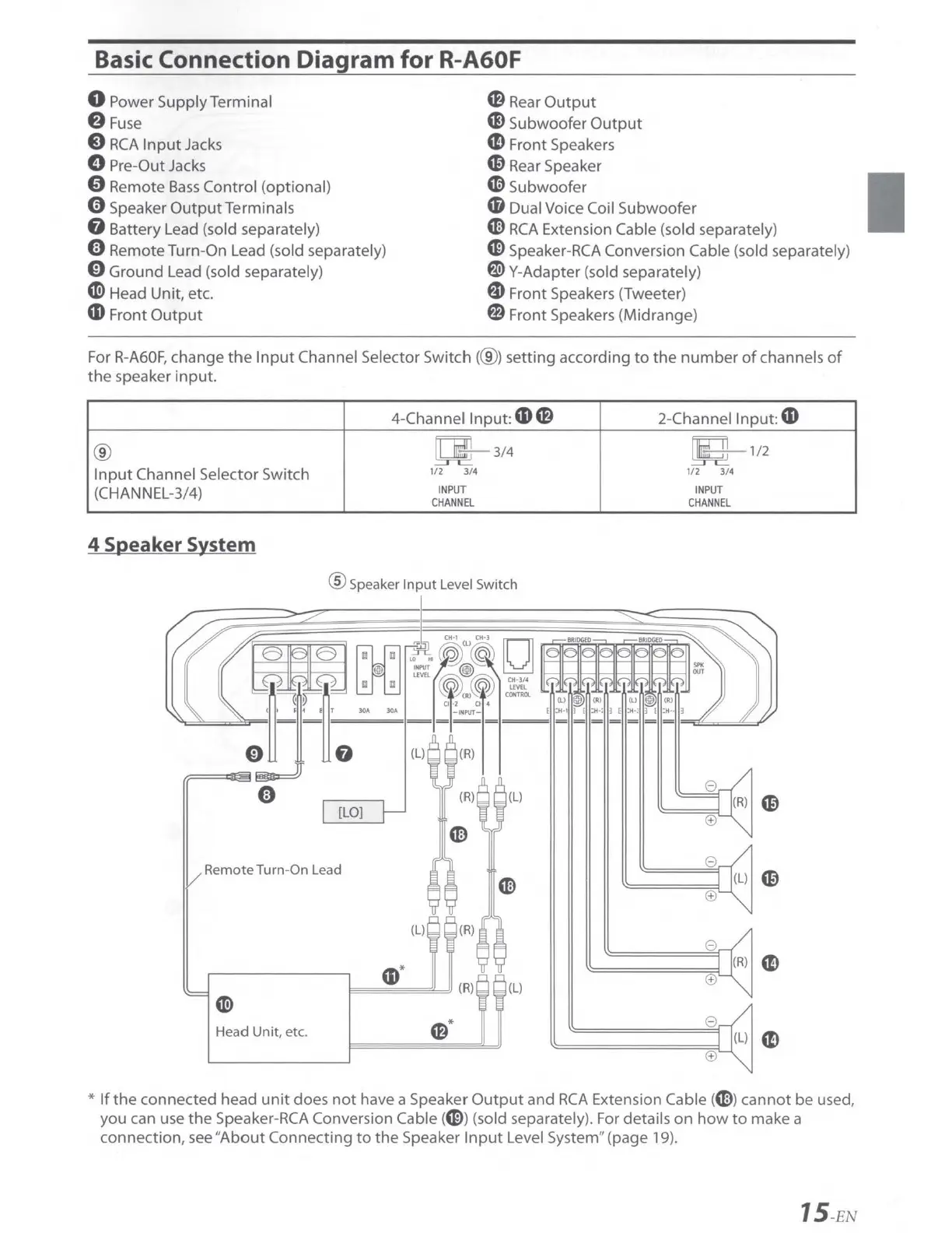
0 Power Supply Terminal
f)
Fuse
8
RCA
Input
Jacks
0 Pre-Out Jacks
0 Remote
Bass
Control
(opt
ional)
0 Speaker
OutputTerminals
G Battery Lead (sold separately)
CB
Rear
Output
G)
Subwoofer
Output
CD
Front Speakers
C0
Rear Speaker
«l>
Subwoofer
CD
Dual Voice Coil
Subwoofer
m
RCA
Extension Cable (sold separately)
0 Remote Turn-On Lead (sold separately)
0 Ground Lead (sold separately)
CD>
Head Unit, etc.
G>
Speaker-RCA Conversion Cable (sold separately)
~ Y-Adapter (sold separately)
G Front Speakers (Tweeter)
CD
Front
Output
fl) Front Speakers (Midrange)
For
R-A60F,
change
the
Input
Channel Selector
Switch(@)
setting according
to
the
number
of
channels
of
the
speaker
input.
4-Channel
Input:
CD
CB
2-Channel
Input:
CD
®
~ 3/4
Ii
ill
1/2
Input
Channel Selector Switch
1/2
3/4
1/2
3/4
(CHANNEL-3/4)
INPUT
INPUT
CHANNEL
CHANNEL
4 Speaker System
® Speaker
Input
Level Switch
[LO]
Remote Turn-On Lead
e
m
(±)
(L)
(R)
e
CD*
(R) (L)
(±)
en>
Head
Unit
, etc.
CB
*
e
(±)
*
If
the
connected head
unit
does
not
have a Speaker
Output
and
RCA
Extension Cable (ml
cannot
be used,
you can use
the
Speaker-
RCA
Conversion Cable (G)) (sold separately). For details
on
how
to
make a
connection, see
"About
Connecting
to
the
Speaker
Input
Level System" (page 19).
15
-EN