Description and operation
General Description of the Circuit breaker
© ALSTOM 2010. All rights reserved. Informat
this document is indicative only. No
relied on that it is complete or correct or will apply to any particular project. This will depend on the technical and commercial circumstances. It is
change without notice. Reproduction, use or disclosure to
third parties, without express writt
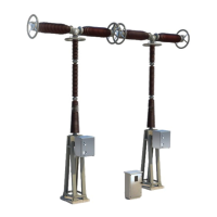
Supports the pole sheathes
Supports the pole sheathes
Distance between phases :
<1500 = supports beam fitted with 2 feets
> 1500 = supports beam fitted with 3 feets
 Loading...