EasyManua.ls Logo

Alstom FKG1X - Operating Device of Circuit-Breaker

Alstom FKG1X
274 pages
To Next Page IconTo Next Page
To Previous Page IconTo Previous Page
Loading...
Description and operation
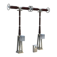
General Description of the Circuit breaker
G12
-
-0
01EN10
6/12
02--2011
© ALSTOM 2010. All rights reserved. Informat
ion contained in
this document is indicative only. No
representati
on or
warrant
y is
given or should
be
relied on that it is complete or correct or will apply to any particular project. This will depend on the technical and commercial circumstances. It is
provided without liabili
ty and
is subject to
change without notice. Reproduction, use or disclosure to
third parties, without express writt
en authority, is
strictly prohibited.
GRID
Circui
t
break
er
assem
bly
control section
Illustration
15
14
26
27
15
13
1
1
26
Components
The
followin
g
table
lists
the
princip
le
compon
ents
of
the
operatin
g
mecha-
nisms:
M
a
r
k
C
o
m
p
o
n
e
n
t
F
u
n
c
t
i
o
n
1
1
CB
Ope
ra
tin
g
Me
ch
an
is
m
Pro
vi
de
s
co
ntr
ol
of
the
CB
1
3
In
s
p
e
c
t
i
o
n
p
o
r
t
U
s
e
d
to
v
i
s
u
a
l
l
y
i
n
s
p
e
c
t
th
e
p
o
s
i
ti
o
n
of the optical CB positional indicator
(See Para.: CB position indicator
status’)
1
4
I
n
s
p
e
c
t
i
o
n
p
o
r
t
U
s
e
d
t
o
v
i
s
u
a
l
l
y
i
n
s
p
e
c
t
t
h
e
p
o
s
i
-
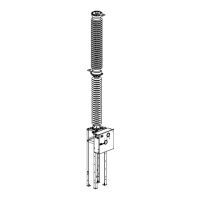
tion(s) of the various earthing switch
controls.
(See
Par
a.
Dis
con
nec
tor
Swit
ch
position indicator
status’
)
15
Op
er
at
in
g
me
ch
an
is
ms
fo
r
the
va
rio
us
di
sc
on
ne
cto
r
switches
Provides control of the busbar earth-
ing switch, the startup switch and the
earthing
switch(e
s).
26
Lo
w
V
ol
tag
e
(L
V)
Ca
bi
ne
t
Ho
us
es
the
lo
w
vo
lta
ge
fun
cti
on
s
for
the whole CB.
2
7
S
y
n
o
p
ti
c
d
i
a
g
ra
m
U
s
e
d
to
g
iv
e
a
v
is
u
a
l
i
n
d
i
ca
ti
o
n
o
f
th
e
overall status of the CB.

Related product manuals