Do you have a question about the Altair WBS-200 and is the answer not in the manual?
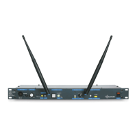
Details switches, controls, and connectors on the front of the base station.
Description of the headset connection port and its pin assignments.
Explains the function of the volume control for headphone listening level.
Covers controls for muting microphones and buzzers remotely.
Describes the function and operation of the call switch.
Details the talk switch and sidetone adjustment controls.
Explains the controls for the program input signal.
Covers radio registration and in-range status indicators.
Describes the unit's power switch functionality.
Details the power input and fuse holder location on the rear panel.
Explains the switch for selecting program input signal type (MIC/LINE).
Details the XLR connector for program input.
Explains the switch for selecting program output signal type.
Details the XLR connector for PA output.
Describes the control for adjusting program output signal level.
Explains the switch for intercom line terminal impedance.
Details the XLR connectors for intercom lines.
Covers the switch for routing radio audio to intercom lines.
Explains the switch for linking intercom channels A and B.
Warning about high voltages inside the unit and the need for disconnection.
Warning to protect the unit from liquid ingress and heat sources.
Instructions for unpacking and inspecting the unit for shipping damage.
Recommendations for rack mounting the base station.
Steps for replacing the fuse in the unit.
Important caution regarding correct mains voltage and fuse type.
Guidance on positioning antennas for optimal performance and avoiding interference.
Details the pin configuration for the XLR program input connector.
Instructions for connecting unbalanced audio sources to the program input.
Illustrates connections for ground-referenced sound sources.
Illustrates connections for floating sound sources.
Shows balanced input connection for floating sound sources.
Details the pin configuration for the XLR PA output connector.
Instructions for connecting to unbalanced destinations from the PA output.
Illustrates PA output connections for ground-referenced destinations.
Illustrates PA output connections for floating destinations.
Shows balanced PA output connection for floating destinations.
Shows balanced PA output connection for ground-referenced destinations.
Details the pin assignments for intercom line connections.
Guidelines to avoid ground loops and minimize noise in intercom connections.
Describes the E-200 series system, base station modes, and connectivity.
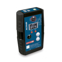
Details compatibility with beltpacks and wired intercom systems.
Explains the global mute functions for microphones and buzzers.
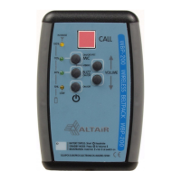
Details how to connect a headset and microphone to the master station.
Explains the control for adjusting headphone listening volume.
Covers controls for remotely muting all mics and buzzers in the system.
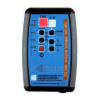
Describes the function and operation of the call switch.
Details the ON/OFF and Push-to-Talk (PTT) modes for the microphone.
Explains the control for adjusting the level of one's own voice heard in headphones.
Explains the switch for enabling/disabling the program input signal.
Describes the control for adjusting the program input signal level.
Steps for registering and deregistering wireless beltpacks with the base station.
Explains the function of the in-range indicator LEDs for beltpacks.
Explains the function and importance of the intercom line impedance switch.
Explains the switch for linking intercom channels A and B.
Covers the switch for routing radio audio to intercom lines.
Describes the control for adjusting program output signal level.
Explains the switch for selecting the program output signal source.
Details the optional input transformer for improved signal isolation.
Details the optional output transformer for improved signal isolation.
Describes the optional directional antenna for extended range.
Advises that special operations should be performed by a qualified technician.
Warning about high voltages even when the unit is off, if connected to mains.
Precaution regarding moisture and liquid ingress when the unit is open.
Instructions to remove specific links before transformer installation.
Steps for physically installing the input transformer onto the PCB.
Instructions to remove specific links before output transformer installation.
Steps for physically installing the output transformer onto the PCB.
Details how to adjust microphone preamplifier gain using jumpers (30/40 dB).
Explains how to enable/disable phantom power using jumper JP3 for microphones.
Lists technical specifications related to the intercom line impedance and levels.
Details general system specifications like voltage, dynamic range, and cable length.
Provides technical details for the preamplifier section.
Lists specifications for the headset amplifier output power and frequency response.
Details the output impedance and nominal level for the PA output.
Lists technical specifications for the program input impedance and levels.
Provides technical details regarding radio frequency, modulation, and sensitivity.
Details the mains voltage, power supply, protections, and requirements.
Lists the reference numbers for optional accessories like transformers and antennas.
Specifies the physical dimensions and weight of the unit.
Outlines the warranty period, coverage, and exclusions.
Instructions for requesting technical service, including serial number requirement.
| Power Consumption (Max) | 30W |
|---|---|
| Housing Material | Metal |
| Type | Base Station |
| Modulation | DECT |
| Operating Voltage | 100-240 VAC, 50-60 Hz |