Do you have a question about the Altec Lansing 9441A and is the answer not in the manual?
Details on connecting the amplifier to 120V AC power.
Procedures for re-strapping the power transformer for 220/240V AC.
Information on installing the amplifier in a standard 19-inch equipment rack.
Guidelines for ensuring adequate ventilation to prevent overheating.
Details on balanced and unbalanced input connection options.
Information on using parallel XLR and phone connectors for line output.
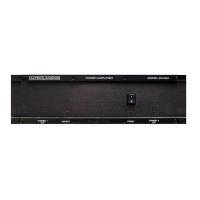
How to make output connections using the terminal barrier strip.
Importance of speaker wire size for sound quality and power loss calculation.
Method to calculate power loss in speaker cables for 8-ohm loads.
How to calculate power loss for 4-ohm loads based on 8-ohm calculations.
Explanation of damping factor and its role in controlling speaker cone movement.
How each channel protects its load from transients, DC, and subsonic signals.
Explanation of the amplifier's current-limiting and protection features.
Meaning of the "PROTECT" LED and its indication of thermal protection or internal fault.
How to operate the amplifier in dual mode with independent channels.
Steps for operating the amplifier in bridge mode for higher power output.
Amplifier's gain levels in dB for different modes and impedances.
Input signal levels required to achieve rated output power.
The highest input signal level the amplifier can handle.
The impedance presented by the amplifier's inputs.
How input polarity relates to output signal polarity.
The amplifier's phase shift characteristics at different frequencies.
Total Harmonic Distortion levels under various conditions.
Intermodulation Distortion levels using the SMPTE standard.
The rate at which the output voltage can change.
The amplifier's ability to control speaker movement.
Signal leakage between channels.
The level of unwanted noise generated by the amplifier.
Summary of amplifier protection features like shorted outputs and over-temperature.
Protection against startup/shutdown transients, DC faults, and subsonic signals.
Describes the conventional heatsink cooling method.
Details the amplifier's output stage design (e.g., true complementary symmetry).
Information on the amplifier's output transistors and their ratings.
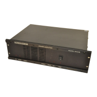
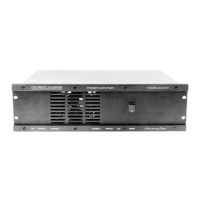
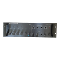
Lists the front and rear panel controls and switches.
Explains the function of front panel LEDs like Power, Clip, and Protect.
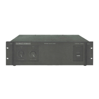
Details input and output connection types and power cord.
Specifies the type of fuse used in the amplifier for 120V AC.
Lists voltage, frequency, and power consumption ratings.
Physical dimensions of the amplifier for rack mounting.
The weight of the product for shipping purposes.
The actual weight of the amplifier.
The color of the amplifier's chassis and front panel.
Details about the amplifier's chassis and front panel construction.
Lists items included with the amplifier, like jumpers and manuals.
List of tools and equipment required for servicing.
Step-by-step guide for adjusting bias trimpots.
How to order replacement components for the amplifier.
Instructions for sending the unit for factory repair.
Contact information for technical support and application assistance.
List of tools and equipment required for servicing.
Step-by-step guide for adjusting bias trimpots.
How to order replacement components for the amplifier.
Instructions for sending the unit for factory repair.
Contact information for technical support and application assistance.
Continuation of the component parts list with more items.
Continuation of the component parts list with more items.
Continuation of the component parts list with more items.
Continuation of the component parts list with more items.
| Input Impedance | 10k ohms |
|---|---|
| Signal to Noise Ratio | 100 dB |
| Damping Factor | 200 |
| Power Output | 400 watts RMS per channel into 4 ohms |
| Frequency Response | 20Hz - 20kHz |
| Total Harmonic Distortion | 0.1% |
| Type | Stereo Power Amplifier |