General instructions
Turn-on
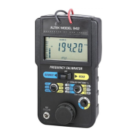
Each time the Model 942 is turned on, the LCD will
display all segments for about 1 second. It then
displays the currently selected waveform (Source
Mode) for approximately 3 seconds.
1) Move the power switch to SOURCE or READ. All
segments on the LCD are turned on during self
test.
2) (SOURCE MODE ONLY) The display will indicate
the selected waveform for 3 seconds. Repeatedly
press or press and hold the SCROLL/STORE
pushbutton to change to the desired waveform.
3) (SOURCE MODE ONLY) The three QUIK-CHEK
frequency outputs will be the same as previously
stored. Each time a different range is selected,
the three QUIK-CHEK outputs for that range will
be recalled.
4) Move the mode switch to RANGE and repeatedly
press or press and hold the SCROLL pushbutton
to change to the desired frequency range.
5) Return the mode switch to FREQ/TRIG to source
or read frequency signals.
Connections
The Model 942 has built-in test leads with alligator
clips for attachment to instruments or sensors with
terminal blocks or flying leads. An optional BNC
connector attaches to instruments or sensors
equipped with BNCs for fast connections.
Troubleshooting
Changing the batteries
Low battery is indicated by BAT on the LCD Display.
Approximately 10 Hours of operation remain before
the LCD goes blank and the Model 942 shuts itself
down. Turn the 942 off, loosen the three captive
screws securing the battery compartment cover. The
six “AA” batteries are easily removed and replaced.
Replace the battery compartment cover, tighten the
screws and turn on when ready to use.
Reset
The Model 942 may be reset from the front panel to
factory default settings. This will reset all the “QUIK-
CHEK” memories to display 1000 and will set the
output and trigger levels to 1 V p-p.
1) Press and hold the SCROLL/RESET pushbutton
while turning the Model 942 on to SOURCE or
READ
2) Keep pressing the STORE pushbutton for 10
seconds
3) All segments on the LCD will remain displayed
until the Model 942 has been reset
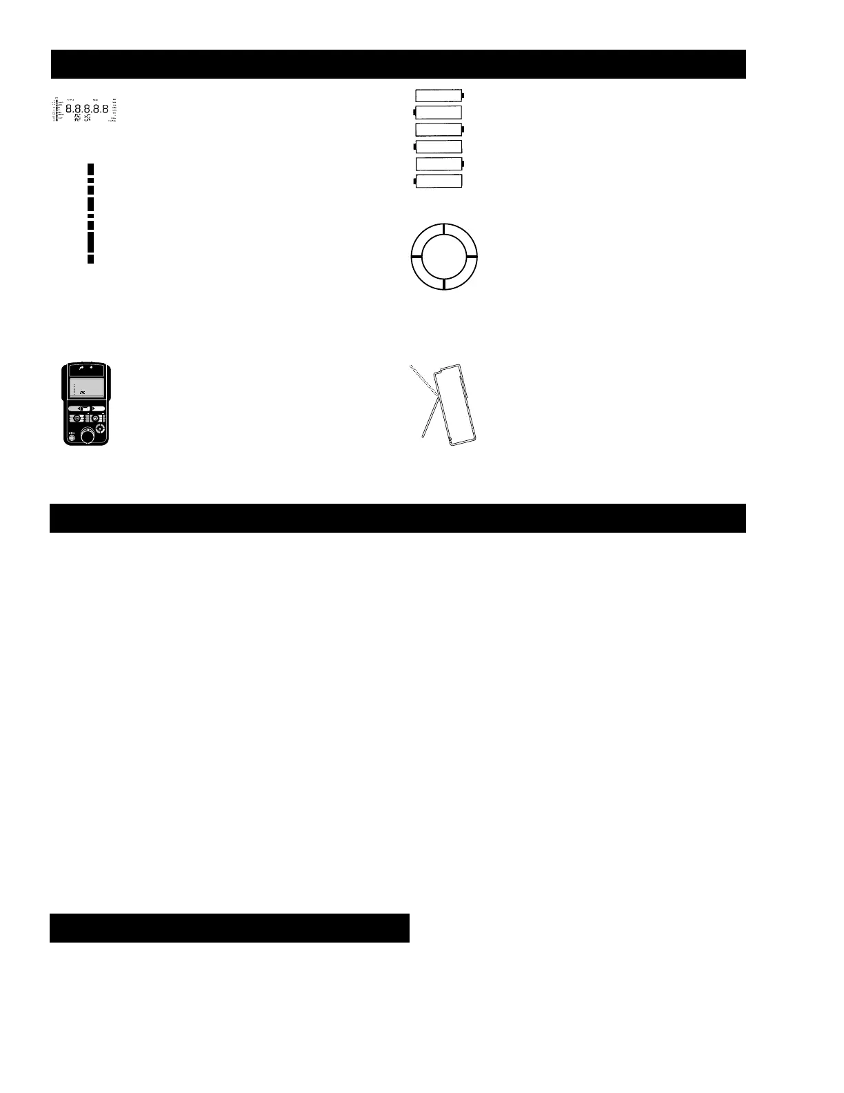
Field and bench use
The Model 942 comes with a carrying case and a
built-in tilt stand/hanger. The 942 is held securely in
the case by Velcro® even with the carrying case
open. The carrying case also has a snap-on belt
loop which can also be looped around a pipe or rail.
The tilt stand is easily raised by pulling the stand until
it locks into place. The stand can also be reversed for
use as a hanger to suspend the Model 942.
Reading frequency
In order for the Model 942 to obtain the most accurate readings
you must correctly set the ATTENUATOR, TRIGGER LEVEL and
RANGE. Signals from 50mV to over 240 volts p-p, with or without
DC offsets can be displayed.
Symptom Check Solution
GATE on LCD,
Display shows
0.0
OVER/UNDER
Range on LCD
Unstable reading
Connections
Attenuator
Input level
DC Offset
Range
Trigger Level
Make sure all power and signals
are properly connected.
Set at x1 for signals from 50mV to
12 Volts p-p, x10 for signals over
12 V p-p.
Turn knob until GATE pulses and
readings are displayed.
Small signals with large DC offsets
may require a series capacitor.
Move the mode switch to RANGE
and press the SCROLL/RESET
pushbutton until the correct range
appears in the LCD.
Turn knob until GATE pulses and
readings are displayed.
Sourcing frequency
Some receivers can only detect signals that go from positive to
negative (Sine Wave or Zero Crossing Square Waves) while other
receivers require only positive signals (Zero Based Square
Waves). The Model 942 provides a choice of these outputs.
Symptom Check Solution
Lack of
Response
Wrong Range
Lack of
response or
jittery signal
Connections
Waveform
Range
Peak Voltage
Make sure all power and signals
are properly connected.
Turn Model 942 OFF and back on
to SOURCE. Repeatedly press the
SCROLL/STORE pushbutton until
the correct waveform is displayed.
Move the mode switch to RANGE
and press the SCROLL/RESET
pushbutton until the correct range
appears in the LCD.
Move the mode switch to LEVEL
and turn the knob while observing
the logarithmic bar graph to match
the input level of the device being
calibrated. Return the mode switch
to FREQ.
To Convert From: To: Divide By:
CPM Hz 60
CPH Hz 3600
To Convert From: To: Multiply By:
Hz CPM 60
Hz CPH 3600
CPM/CPH frequency conversions
 Loading...