Frequency output
Source
1) Move the POWER switch to SOURCE
2) Move the mode switch to RANGE and repeated-
ly press or press and hold the SCROLL/STORE
pushbutton to change to the desired frequency
range. Return the mode switch to FREQ.
3) Move the mode switch to LEVEL (AMPLITUDE)
and turn the Digipot (Knob) until the logrithmic
bargraph on the display reaches the desired
level.Return the mode switch to FREQ.
4) Connect the Model 942 to the input terminals of
the instrument or meter to be calibrated
5) Adjust the digital pot to the desired output value
or Quik-Chek with previously stored frequency
outputs (see below)
Whenever SOURCE mode is selected the word
SOURCE will appear on the LCD display. To change
the output value, turn the speed sensitive digital pot.
Turning the pot slowly will cause a gradual change
in the output. A faster change will occur when the
pot is turned faster. This function operates in all
three output positions (HI, SET & LO).
Store
1) Switch to HI or LO
2) Turn the digital pot to desired value
3) Press the STORE/SCROLL pushbutton
The LCD will flash once to show that the value
was saved
If a value is in the SET position and you want that
value stored in HI or LO, press and hold the
STORE/SCROLL pushbutton while moving the
switch to HI or LO. The display will flash once to
indicate the value has been stored. Then release
the STORE/SCROLL button.
Quik-Chek
Any time you need a stored value just throw the
Quik-Chek switch. Any value in the frequency range
may be stored in HI & LO. The Model 942
remembers the HI, LO and SET values for all
ranges (18 memories) for you with the power on or
off. Each time a different frequency range is select-
ed, the last three Quik-Chek values for that type will
be recalled.
Read frequency
Read
1) Move the POWER switch to READ
2) Move the mode switch to RANGE and repeatedly
press or press and hold the SCROLL/RESET
pushbutton to change to the desired frequency
range. Return the mode switch to TRIG.
3) Switch the MODE switch to LEVEL
(AMPLITUDE) to toggle between x1 & x10
attenuation (Use x1 for signals from 30 mV to 12
V p-p, x10 for signals from 12 V to 240V p-p).
Return the mode switch to TRIG.
4) Connect the Model 942 to the output of the in-
strument or sensor to be measured.
5) Adjust the trigger level to obtain a stable
frequency reading by turning the Digipot (knob).
A bargraph on the display will show the approxi-
mate trigger level.
6) Use the “Quik-Chek” switch to display present
reading, maximum or minimum frequency.
The word GATE will appear on the display whenev-
er the Model 942 is measuring the frequency signal
and will flash each time the displayed reading is
updated.
Period readings
Select Counts-per-Minute (CPM) or Counts-per-
Hour (CPH) to measure slow frequency signals.
Frequencies as low as 0.1 CPM (0.001666 Hz) and
10 CPH (0.002777 Hz) can be measured (See
CPM/CPH frequency conversions for conversion
factors).
Min/max
To read the Maximum or Minimum frequencies since
READ mode was entered, simply switch to MAX or
MIN. The value will appear on the LCD along with
the word MAX or MIN. The MAX/MIN values are au-
tomatically updated and may be viewed at any time
without disturbing the other values. Pressing the
RESET/SCROLL pushbutton will cause the 942 to
stop counting frequencies and will display zeros.
Upon releasing the RESET/SCROLL the Model 942
will display GATE, resume counting frequencies and
update the MAX & MIN values as the measured fre-
quency changes.
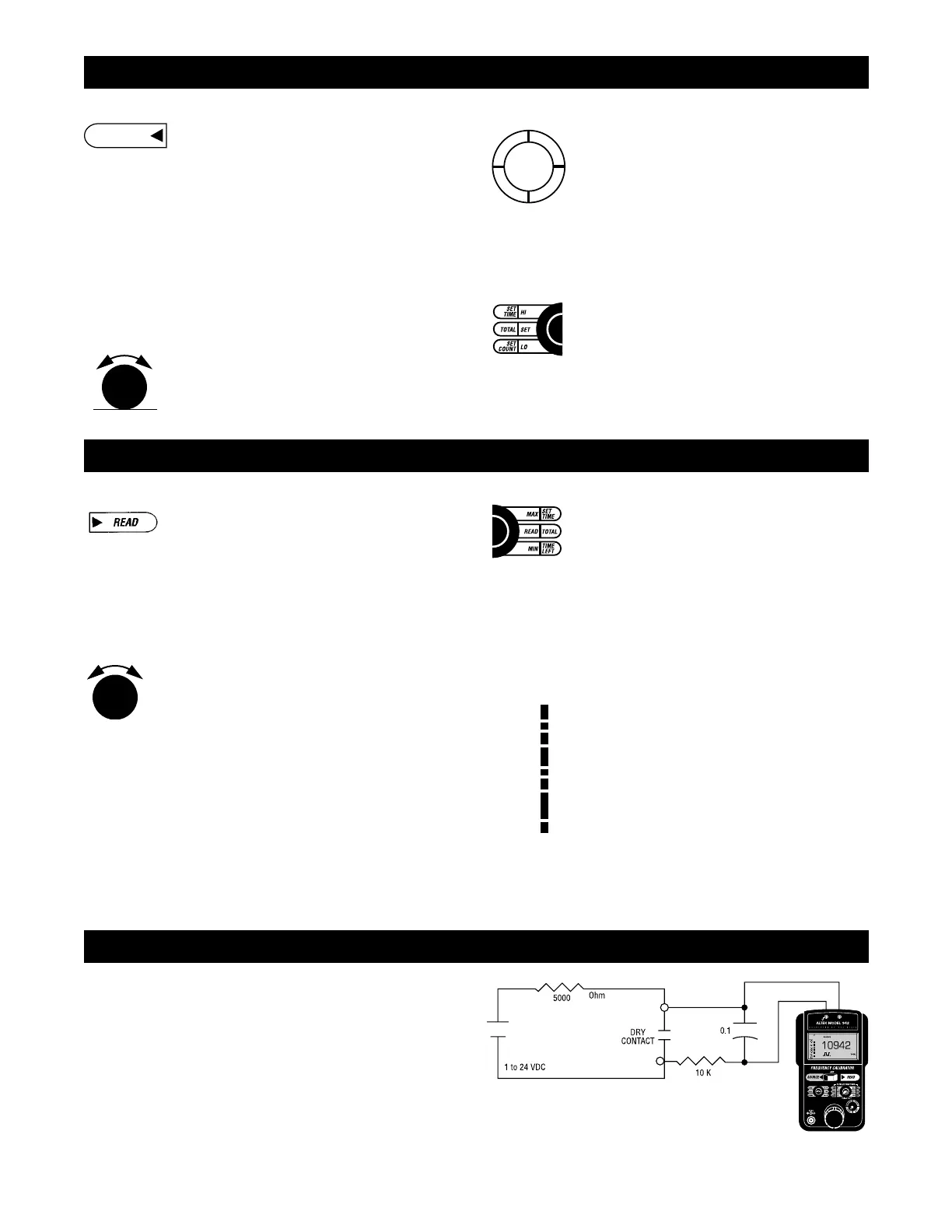
Trigger level
The adjustable TRIGGER LEVEL is used in mea-
surements of noisy signals, AC signals superim-
posed on DC levels and to select Voltage threshold
for all other signals. The bargraph on the display
shows the approximate level from 0 to over 12 V
positive peak with the attenuator set at x1. This
bargraph should be read as 0 to over 120 V positive
peak with the attenuator set at x10. For quickest
readings, determine or estimate the voltage level to
be detected and set the ATTENUATOR and TRIG-
GER LEVEL to match.
Out of range signals
Frequencies above or below those available for the
currently selected range will be indicated by OVER
and UNDER on the display (See Troubleshooting).
 Loading...