5. Separate the wall mounting pieces. Mount the top and
bottom leg stand pieces (Figure 1) onto the UBC1319AA00
as shown in Figure 2.
6. You can now mount the UBC1319AA00 onto the wall using
the screws installed in Step 4.
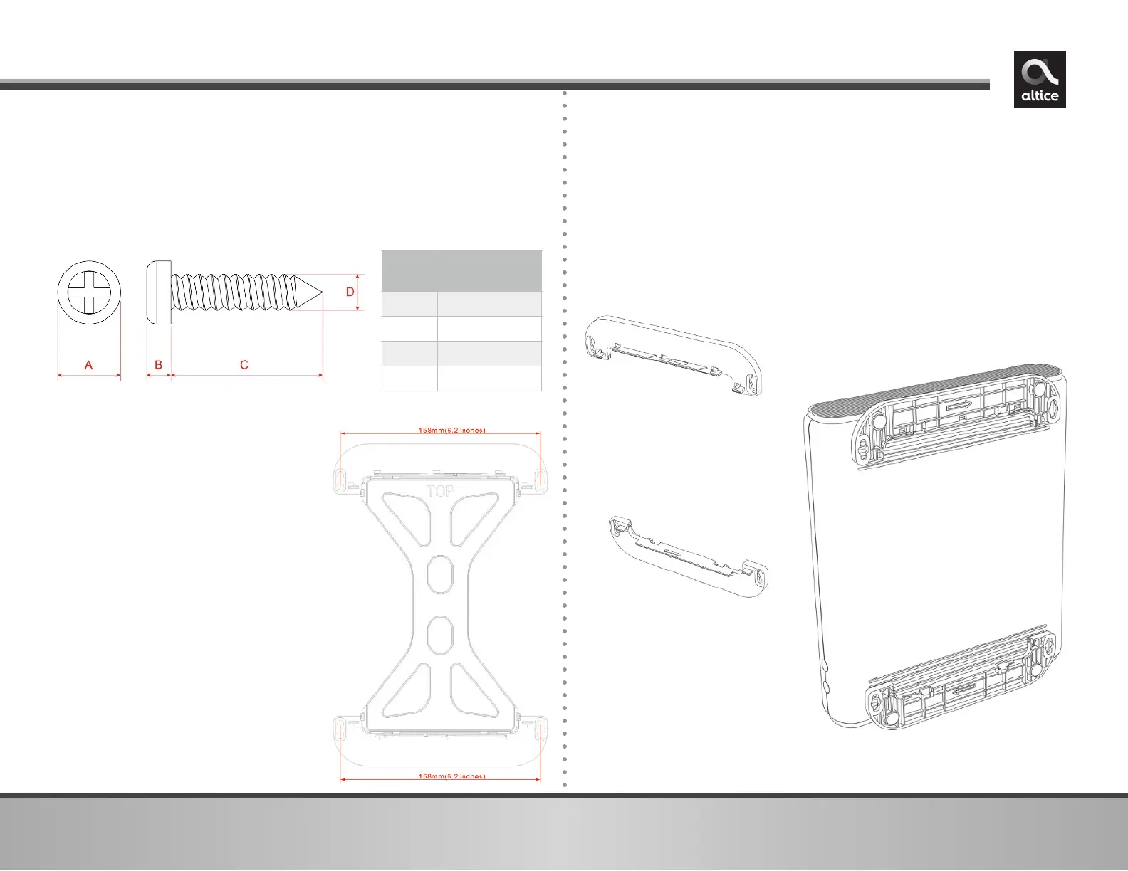
2. Fit the 2 leg stand pieces
together with the wall mount
template as represented in the
graphic to the right.
3. Place this on the wall and use it
as a template to mark the wall
for the appropriate placement
of the screws.
4. Install the 2 sets of screws on
the wall (158 mm or 6.2 inches
apart).
NOTE: The screws should protrude
from the wall so you can fit the
device between the head of the
screws and the wall. If you install
the screws in drywall, use hollow
wall anchors to ensure the unit
does not pull away from the wall
due to prolonged strain from the
cable and power connectors.
You can mount the UBC1319AA00 on a wall by following the
steps below:
1. You will need 4 round or pan head screws with the following
measurements: