FORM CPU-95 II 4-08
2
CPU-95 DIGITAL IGNITION SYSTEM
*NOTE: If using Ignition
Module 791958-16, use
one of the red coil options:
591010, 591010-S or
591012.
NOTE: The enclosure width
is 1 inch larger than the
CPU-90 unit, ½ inch on each
side.
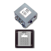
2.0 SYSTEM COMPONENTS
2.1 The system consists of an Ignition Module, a Display Module, wiring
harnesses, (2) magnetic pickups and cables, a Hall-effect pickup and
trigger magnet (4-cycle engines only), and an ignition coil for each spark
plug; SEE FIGURE 4 for a complete system overview.
2.2 Use one of the following Altronic ignition coils:
● Unshielded coils 501061 or 591010*
● Shielded coils 501061-S or 591010-S*
● Flange coils 591018 or 591012*
● Integral coils 591007, 591011A or 591011B
Refer to the Application List (form CPU-95 AL) for requirement de-
tails and SEE FIGURE 6 (unshielded) and FIGURE 7 (shielded).
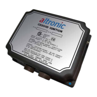
3.0 MOUNTING THE CPU-95 IGNITION MODULE
3.1 SEE FIGURE 17 for physical dimension details. Select a mounting loca-
tion meeting the following requirements:
● On the engine.
● Within 50 ft. of the Display Module.
● Within 7 ft. of the primary junction box.
● The front door of the Ignition Module should be easily accessible and
free to swing open.
● The maximum ambient temperature must not exceed 150°F (65°C).
3.2 The Ignition Module enclosure should be fastened securely to a rig-
id engine bracket using the shock mounts provided.
3.3 When replacing an existing Altronic CPU-90 system, the CPU-95 Igni-
tion Module can be mounted in place of the CPU-90 unit; the mount-
ing footprint is identical to facilitate the changeover.
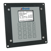
4.0 MOUNTING THE CPU-95 DISPLAY MODULE
4.1 Mount the CPU-95 Display Module inside a control panel or to a suit-
able at surface preferably off the engine in such a manner as to
minimize exposure to vibration. The Display Module should be
mounted so that the display is at a convenient viewing height. SEE
FIGURE 18 for mounting dimensions. A NEMA 3R housing (720004-1)
is also available as an alternative mounting option for the Display
Module (FIGURE 19).
4.2 The Display Module should be mounted within 50 feet (15 m) of the
Ignition Module which is to be mounted on the engine.
 Loading...