INSTALLATION INSTRUCTIONS
CPU-95
DIGITAL IGNITION SYSTEM
MODELS 791950-8/16/18, 791952-18, 791958-16
DEVIATION FROM THESE INSTRUCTIONS MAY LEAD TO IMPROPER OP-
ERATION OF THE MACHINE WHICH COULD CAUSE PERSONAL INJURY
TO OPERATORS OR OTHER NEARBY PERSONNEL.
WARNING:
www.altronicinc.com
FORM CPU-95 II 4-08
www.altronicinc.com
1
DEVIATION FROM THESE INSTRUCTIONS MAY LEAD TO IMPROPER
ENGINE OPERATION WHICH COULD CAUSE PERSONAL INJURY TO
OPERATORS OR OTHER NEARBY PERSONNEL.
WARNING:
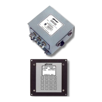
1.0 SYSTEM DESCRIPTION
1.1 The Altronic CPU-95, DC-powered ignition system is a microproces-
sor-based capacitor discharge system designed for application on
natural gas fueled engines. The system features crankshaft-trig-
gered timing accuracy and the capability to vary timing electroni-
cally by several means, including an external 4-20 mA control signal
connected to the optional Display Module. The system is eld-pro-
grammable and offers a variety of advanced control methods, emis-
sions reduction, primary and spark diagnostics, self diagnostics,
serial communications and engine protection features. The system
consists of two main parts: an engine mounted Ignition Module and
an optional user interface Display Module.
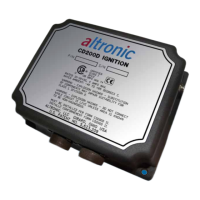
1.2 Various models of the Ignition Module are available:
791950-8 8-outputs, standard
791950-16 16-outputs, standard
791950-18 18-outputs, standard
791952-18 18-outputs, dual capacitor
791958-16 16-outputs, Varispark™ extended duration
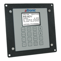
1.3 The optional Display Module has a graphical, back-lit LCD display
that shows the operating status, engine RPM, energy level, single or
double-striking mode, current loop input value and ignition timing.
Additional display screens show set-up and diagnostic information.
1.4 To allow for a simple and economical upgrade of existing Altronic
CPU-90 installations, the CPU-95 utilizes the same ignition box mount-
ing layout, existing Altronic coils, magnetic pickups, Hall-effect
pickup and trigger magnet, pickup cables, primary wiring harness
and junction box(es).
1.5 Power requirement is 24 Vdc, 5 ampere nominal for typical applica-
tions. For Ignition Module 791958-16, use a supply rated for 24 Vdc, 10
amperes. SEE SECTION 9.2 FOR DETAILS.
THE IGNITION SYSTEM MUST BE CONFIGURED PRIOR TO
USE ON AN ENGINE. REFER TO SECTION 9.7 TO VIEW THE
CURRENT CONFIGURATION. REFERENCE FORM CPU-95 PI
FOR INSTRUCTIONS DESCRIBING HOW TO CONFIGURE THE
IGNITION SYSTEM. VERIFY EEPROM PROGRAMMING PRIOR
TO STARTING ENGINE.
WARNING: