8
NO.
CYLS.
Engine
Firing
Angle
SECT. 9.5
DISC
SETTING
SECT. 9.20
SLAVE
ANGLE
IN FIRING ORDER,
OUTPUT A
CONNECTS TO:
10 90°–54° 5+1 54° Second cylinder
12 30°–90° 6+1 30° First cylinder
12 40°–80° 6+1 40° First cylinder
12 50°–70° 6+1 50° First cylinder
12 55°–65° 6+1 55° First cylinder
12 60°–even 6+1 60° First cylinder
12 75°–45° 6+1 45° Second cylinder
12 90°–30° 6+1 30° Second cylinder
16 30°–60° 8+1 30° First cylinder
16 45°–even 8+1 45° First cylinder
16 60°–30° 8+1 30° Second cylinder
9.20 Cylinder CAL:
These numeric entries configure the amount of individual offset timing retard
added to the global timing for each individual output. This feature can be used
to map an evenly spaced timing disc to an odd firing angle engine pattern. En-
try range is 0 to 50 degrees of engine retard. Default settings are 0. Contact
the factory for further details of this feature.
9.21 Energy Flags:
Select one of four output energy settings for the CD200D:
Bit 1 OFF Bit 0 OFF Vcap = 150 volts
Bit 1 OFF Bit 0 ON Vcap = 160 volts
Bit 1 ON Bit 0 OFF Vcap = 170 volts
Bit 1 ON Bit 0 ON Vcap = 180 volts
Default setting is 160 volts at the capacitor. This voltage can only be mea-
sured using a device with an input impedance of 1 megaohm or higher with no
other device connected.
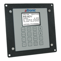
10.0 PC TERMINAL DISPLAY FUNCTIONS
10.1 Engine Speed:
Indicates current speed of the engine in RPM based on disc signal.
10.2 Spark Timing:
Indicates the global spark timing of the engine in degrees before TDC. This
number is the LINE UP ANGLE setting less the TOTAL RETARD. Slight dif-
ferences between this number and the timing reading obtained with a timing
light may occur since the LINE UP ANGLE entered may differ slightly from the
actual angular position of the engine when the input pulse event is received by
the CD200D. In this event, the Spark Timing number should be made to agree
with the timing light by changing the LINE UP ANGLE entry.
10.3 Switch Position:
Indicates the current position of the manual timing switch on the CD200D case.
10.4 Loop Input:
Indicates the value of the external input current loop.
10.5 Observed Disc:
Indicates the number of input events (timing holes, protrusions or magnets) be-
ing recognized by the CD200D unit on the timing disc input signal at this time.
NOTE: Please see page 28 (Addendum)
for further details of CD200D Unit -
791090-xR.
NOTE: Please see page 28 (Addendum)
for further details of CD200D Unit -
791090-xR.
 Loading...