EasyManua.ls Logo

Altronix AL400ULXB - User Manual

Altronix AL400ULXB
2 pages
Print Icon
To Next Page IconTo Next Page
Loading...
Power Supply Voltage Output Selections:
Stand-by Specifications:
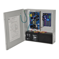
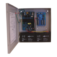
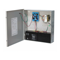
Installation Instructions:
The AL400ULXB should be installed in accordance with article 760 of The National Electrical Code or NFPA 72
as well as all applicable Local Codes.
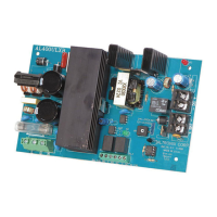
1. Mount the AL400ULXB in desired location/enclosure.
2. Set the AL400ULXB to the desired DC output voltage by setting SW1 (Fig. 2, pg. 2) to the appropriate position
(refer to Power Supply Voltage Output Selections chart).
3.
Connect AC power (115VAC 50/60Hz) to terminals marked [L, G, N] (Fig. 2, pg. 2). Use 18
AWG or larger for all
power connections (Battery, DC output, AC input). Use 22 AWG to 18 AWG for power limited circuits
(AC Fail/Low Battery reporting).
Keep power limited wiring separate from non-power limited wiring (115VAC / 60Hz Input, Battery Wires).
Minimum .25” spacing must be pr
ovided.
4. Connect devices to be powered to terminals marked [ – DC +] (Fig. 2, pg. 2).
5.
Measure output voltage before connecting devices. This helps avoid potential damage.
6. For Access Control applications, batteries are optional. When batteries are not used a loss of AC will result in the
loss of output voltage. When the use of stand-by batteries is desired, they must be lead acid or gel type.
Connect battery to terminals marked [+ BAT – ] (Fig. 2, pg. 2). Use tw
o (2) 12VDC batteries connected in series for
24VDC operation (battery leads included).
AL400ULXB
UL Recognized Power Supply/Charger
Rev. 120600
Agency Listings:
UL Recognized component for: Access Control
System Units (UL 294), P
ower Supplies for use with
Burglar-Alarm Systems (UL 603), Power Supplies
for Fire Protective Signaling Systems (UL 1481).
Input Rating:
Input 115VAC 50/60Hz, 1.45 amp.
Output Rating:
Class 2 Rated power limited output.
12VDC or 24VDC selectable output.
12VDC @ 4 amp or 24VDC @ 3 amp continuous
supply current.
Filtered and electronically regulated output.
Battery Backup:
Built-in charger for sealed lead acid or gel type batteries.
Maximum charge current .7 amp.
Automatic switch over to stand-by battery when AC fails.
Zero voltage drop when switched over to battery backup.
Visual Indicators:
AC input and DC output LED indicators.
Supervision:
AC fail supervision (form "C" contacts).
Low battery and battery presence supervision
(form "C" contacts).
Additional Features:
Short circuit and thermal overload protection.
Board Dimensions (approximate):
4.6”W x 7.5”L x 2.7”H
OPEN SWITCH
CLOSED SWITCH
Switch Detail
--- DC
+
L G N
PTC3
N
C C NO NC C NO
+
BAT ---
DC
24V - OPEN
12V - CLOSED
AC FAIL
RL2
BAT FAIL
RL1
RL3
J1
SW1
3.5A
250V
Fuse
Cover
AC Delay
Fig. 1
Overview:
The AL400ULXB is a power supply/charger that converts a 115VAC 50/60Hz input, into a Class 2 Rated power limited
12VDC or 24VDC output (see specif
ications).
Specifications:
Output Switch Position
12VDC SW1 - CLOSED (Fig. 1, on right)
24VDC SW1 - OPEN (Fig. 1, on right)
Output
4 hr. of Stand-by &
5 Minutes of Alarm
24 hr. of Stand-by &
5 Minutes of Alarm
60 hr. of Stand-by &
5 Minutes of Alarm
12VDC / 40AH Battery
Stand-by = 4.0 amp
Alarm = 4.0 amp
Stand-by = 1.0 amp
Alarm = 4.0 amp
Stand-by = 300mA
Alarm = 4.0 amp
24VDC / 12AH Battery --------
Stand-by = 200mA
Alarm = 3.0 amp
--------
24VDC / 40AH Battery
Stand-by = 3.0 amp
Alarm = 3.0 amp
Stand-by = 1.0 amp
Alarm = 3.0 amp
Stand-by = 300mA
Alarm = 3.0 amp
Question and Answer IconNeed help?

Do you have a question about the Altronix AL400ULXB and is the answer not in the manual?

Overview

The Altronix AL400ULXB is a UL Recognized Power Supply/Charger designed to convert a 115VAC 50/60Hz input into a Class 2 Rated power-limited 12VDC or 24VDC output. It is suitable for various applications including Access Control System Units (UL 294), Power Supplies for use with Burglar-Alarm Systems (UL 603), and Power Supplies for Fire Protective Signaling Systems (UL 1481).

Function Description:

The device acts as a power supply and charger, providing regulated DC power and battery backup capabilities. It features automatic switch-over to a stand-by battery upon AC failure with zero voltage drop. The output voltage is selectable between 12VDC and 24VDC via a switch (SW1). It also includes supervision features for AC failure, low battery, and battery presence, indicated by form "C" contacts. Visual indicators (LEDs) are provided for AC input and DC output status.

Important Technical Specifications:

  • Input Rating: 115VAC 50/60Hz, 1.45 amp.
  • Output Rating:
    • Class 2 Rated power-limited output.
    • Selectable 12VDC or 24VDC output.
    • 12VDC @ 4 amp continuous supply current.
    • 24VDC @ 3 amp continuous supply current.
    • Filtered and electronically regulated output.
  • Battery Backup:
    • Built-in charger for sealed lead acid or gel type batteries.
    • Maximum charge current: 0.7 amp.
    • Automatic switch-over to stand-by battery when AC fails.
    • Zero voltage drop when switched over to battery backup.
  • Supervision:
    • AC fail supervision (form "C" contacts).
    • Low battery and battery presence supervision (form "C" contacts).
  • Additional Features:
    • Short circuit and thermal overload protection.
  • Board Dimensions (approximate): 4.6"W x 7.5"L x 2.7"H.

Stand-by Specifications (for 5 Minutes of Alarm):

  • 12VDC / 40AH Battery:
    • 4 hr. Stand-by: 4.0 amp
    • 24 hr. Stand-by: 1.0 amp
    • 60 hr. Stand-by: 300mA
    • Alarm: 4.0 amp for all durations.
  • 24VDC / 12AH Battery:
    • 24 hr. Stand-by: 200mA
    • Alarm: 3.0 amp
  • 24VDC / 40AH Battery:
    • 4 hr. Stand-by: 3.0 amp
    • 24 hr. Stand-by: 1.0 amp
    • 60 hr. Stand-by: 300mA
    • Alarm: 3.0 amp for all durations.

Usage Features:

  • Installation: The AL400ULXB should be installed according to Article 760 of The National Electrical Code or NFPA 72, and all applicable Local Codes.
  • Mounting: Mount the AL400ULXB in the desired location/enclosure.
  • Voltage Selection: Set the DC output voltage by setting SW1 to the appropriate position (CLOSED for 12VDC, OPEN for 24VDC).
  • AC Power Connection: Connect 115VAC 50/60Hz to terminals marked [L, G, N]. Use 18 AWG or larger for all power connections (Battery, DC output, AC input).
  • Power Limited Wiring: Use 22 AWG to 18 AWG for power-limited circuits (AC Fail/Low Battery reporting). Keep power-limited wiring separate from non-power-limited wiring (115VAC / 60Hz Input, Battery Wires). A minimum 0.25" spacing must be provided.
  • Device Connection: Connect devices to be powered to terminals marked [– DC +].
  • Voltage Verification: Measure output voltage before connecting devices to avoid potential damage.
  • Battery Connection: For Access Control applications, batteries are optional. If stand-by batteries are desired, they must be lead acid or gel type. Connect batteries to terminals marked [+ BAT –]. For 24VDC operation, use two (2) 12VDC batteries connected in series (battery leads included).
  • Signaling Notification: Connect appropriate signaling notification devices to AC FAIL & BAT FAIL supervisory relay outputs. For fire alarm, burglar alarm, or access control applications, the "AC Fail" relay should be used to visually indicate AC power status. A 6-hour delay for AC fail reporting can be set by cutting the "AC Delay" jumper.

Visual Indicators (LED Diagnostics):

  • Red (DC) ON, Green (AC) ON: Normal operating condition.
  • Red (DC) ON, Green (AC) OFF: Loss of AC, Stand-by battery supplying power.
  • Red (DC) OFF, Green (AC) ON: No DC output.
  • Red (DC) OFF, Green (AC) OFF: Loss of AC. Discharged or no stand-by battery. No DC output.

Terminal Identification:

  • L, G, N: Connect 115VAC 60 Hz. (L to hot, N to Neutral, G to ground).
  • – DC +: 12VDC @ 4 amp or 24VDC @ 3 amp continuous power-limited output.
  • AC Fail (NC, NC, NO): Indicates loss of AC power. Relay normally energized when AC power is present. Contact rating 1 amp @ 28VDC.
  • BAT Fail (NC, C, NO): Indicates low battery condition. Relay normally energized when DC power is present. Contact rating 1 amp @ 28VDC.
  • + BAT –: Stand-by battery connections. Maximum charge current 1.2 amp.

Maintenance Features:

  • Annual Testing: The unit should be tested at least once a year for proper operation.
  • Output Voltage Test: Under normal load conditions, check the DC output voltage for the proper level (refer to the Power Supply Voltage Output Specifications chart).
  • Battery Test: Under normal load conditions, check that the battery is fully charged. Verify the specified voltage at both the battery terminal and the board terminals marked [+ BAT –] to ensure no break in the battery connection wires.
  • Maximum Charging Current: The maximum charging current under discharge is 0.7 amp.
  • Battery Life: Expected battery life is 5 years; however, it is recommended to change batteries in 4 years or less if needed.

Altronix AL400ULXB Specifications

General IconGeneral
BrandAltronix
ModelAL400ULXB
CategoryPower Supply
LanguageEnglish

Related product manuals