AL125UL • AL125ULX • AL125ULP • AL125ULE
Access Control Power Supply/Chargers
Overview:
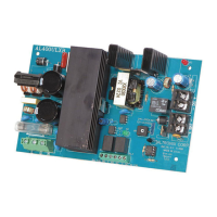
AL125UL Series power-limited Power Supply/Chargers convert 115VAC 50/60Hz input into two individually PTC pro-
tected 12VDC or 24VDC outputs (see specifications). They are intended for use in applications requiring UL Listing for
Access Control (UL294) and applications requiring an interface with Fire Alarm Control Panels.
Specifications:
Agency Listings:
• UL Listed for Access Control Systems (UL294).
CUL Listed - CSA Standard C22.2 No.205-M1983,
Signal Equipment.
• MEA - NYC Department of Buildings Approved.
• NFPA 101 (Life Safety).
Input:
• AL125UL, AL125ULX - 115VAC 50/60 Hz, 0.6A.
• AL125ULP, AL125ULE - 24VAC @ 40VA.
Output:
• Two (2) 12VDC or 24VDC, Class 2 Rated
Power-Limited Outputs.
• 1A total supply current @ 12VDC or 24VDC
(AL125UL & AL125ULX).
• 1A total supply current @ 12VDC, 0.5A total
supply current @ 24VDC (AL125ULP & AL125ULE).
• Filtered and electronically regulated output.*
Battery Backup:
• Built-in charger for sealed lead acid or
gel type batteries.
• Maximum charge current: 400mA.
• Automatic switch over to stand-by battery when AC fails.
Special Features:
• AC power and unit status indicator on the front panel.
• Normally Open [NO] trigger input.
• Supervised Fire Alarm Disconnect (Latching w/reset
or Non-Latching).
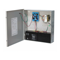
Configurations:
• AL125UL - includes power supply, transformer,
cam lock, and enclosure.
8.5” x 7.5” x 3.5” (215.9mm x 190.5mm x 88.9mm).
Accommodates one (1) 12VDC/4AH battery.
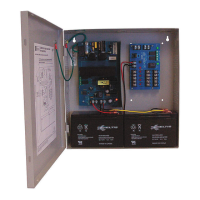
• AL125ULP - includes power supply, 24VAC/40VA
plug-in transformer, cam lock, and enclosure.
8.5” x 7.5” x 3.5” (215.9mm x 190.5mm x 88.9mm).
Accommodates one (1) 12VDC/7AH battery or
two (2) 12VDC/4AH batteries.
• AL125ULE - includes power supply, cam lock,
and enclosure.
8.5” x 7.5” x 3.5” (215.9mm x 190.5mm x 88.9mm).
Accommodates up to two (2) 12VDC/4AH batteries.
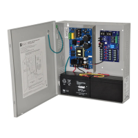
• AL125ULX - includes power supply, transformer,
cam lock, and enclosure
13.5” x 13” x 3.25” (342.9mm x 330.2mm x 82.55mm).
Accommodates up to two (2) 12VDC/7AH batteries.
*Note: When unit is powered by battery back up (AC Fail condition), the voltage range is 9.3V-13.2V and
19.55V-26.4V for 12 and 24 volt operation respectively.
Power Supply Output Specifications: (AL125UL, AL125ULX)
Output VDC Switch Position Max. Stand-by Load DC Max. Alarm Load DC Battery (optional)
12VDC SW2 OFF 1A 1A 12VDC
24VDC SW2 ON 1A 1A 24VDC
Power Supply Output Specifications: (AL125ULP, AL125ULE)
Output VDC Switch Position Max. Stand-by Load DC Max. Alarm Load DC Battery (optional)
12VDC SW2 OFF 1A 1A 12VDC
24VDC SW2 ON 0.5A 0.5A 24VDC
Stand-by Specifications:
Output
4hr. of Stand-by &
5 min. of Alarm
12VDC / 4AH Battery 0.5A / 1A
24VDC / 4AH Battery 0.5A / 1A
Output
4hr. of Stand-by &
5 min. of Alarm
12VDC / 7AH Battery 1A / 1A
24VDC / 7AH Battery 1A / 1A
AL125ULseries - 1 -
Available from A1 Security Cameras
www.a1securitycameras.com email: sales@a1securitycameras.com