Overview:
Altronix SMP3 power supply/charger converts low voltage AC input into 6VDC, 12VDC or 24VDC @ 2.5A of
continuous supply current (see specifications). This general purpose power supply has a wide range of
applications for access control, security and CCTV system accessories that require additional power.
Specifications:
* Specified at 25˚C ambient.
Voltage Output/Transformer Selection Table:
Output
Voltage
Switch Position
Transformer Requirements
(Recommended Altronix Part Numbers)
SW1 SW2
6VDC ON OFF 16VAC / 40VA (TP1640)
12VDC OFF OFF 16VAC / 40VA (TP1640), 24VAC or 28VAC / 100VA (T2428100)
24VDC OFF ON 28VAC / 100VA (T2428100)
Note: Transformers with higher power (VA) ratings may be used for all output voltages selected above
provided the input voltage does not exceed 28VAC or 45VDC.
Installation Instructions:
SMP3 should be installed in accordance with The National Electrical Code and all applicable Local Regulations.
1. Mount SMP3 in the desired location / enclosure (mounting hardware included).
2. Set DC output voltage with switches (refer to Voltage Output/Transformer Selection Table).
3. Connect proper transformer to the terminals marked [AC]
(refer to Voltage Output/Transformer Selection Table).
Use 18 AWG or larger for all power connections (Battery, DC output).
4. Measure output voltage before connecting devices. This helps avoiding potential damage.
5. Connect devices to be powered to the terminals marked [+ DC –].
6. When the use of stand-by batteries is desired, they must be lead acid or gel type.
Connect battery to the terminals marked [+ BAT –] (battery leads included).
Use two (2) 12VDC batteries connected in series for 24VDC operation.
Note: When batteries are not used, a loss of AC will result in the loss of output voltage.
CAUTION: Do not touch exposed metal parts.
Shut branch circuit power before installing or servicing equipment.
There are no user serviceable parts inside. Refer installation and servicing to qualified service personnel.
Input:
• 16VAC to 28VAC
(Voltage Output/Transformer Selection Table).
Output:
• 6VDC, 12VDC or 24VDC selectable output.
• Thermal overload and short circuit protection.
• 2.5A continuous supply current*.
• Filtered and electronically regulated output.
Battery Backup:
• Built-in charger for sealed lead acid or
gel type batteries.
• Maximum charge current 350mA.
• Automatic switch over to stand-by battery.
• Battery short circuit protection (circuit breaker).
Additional Features:
• AC input and DC output LED indicators.
• Extremely compact design.
• Includes battery leads.
• Snap Track compatible
(order Altronix model #ST3).
• DIN Rail Mount version available
(order Altronix model #DPS3).
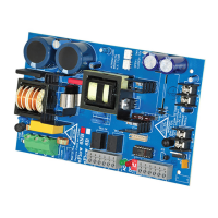
Board Dimensions (W x L x H approximate):
3” x 3.5” x 2” (76.2mm x 88.9mm x 50.8mm)
SMP3
Power Supply/Charger
Installation Guide