Page 2
1
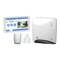
Unpack the Connect+ Hub with your new
security system (see gure A above). We have
already set up a new security account on your
behalf. You will not need to modify the Hub
communicaons or the sensors provided in the
box, each sensor is already enrolled and will
communicate with and through your Connect+ Hub
aer you provide power and Internet connecons.
2
Find a locaon for the panel, keeping in mind
it needs AC power and a local network connecon.
The long-range, encrypted wireless receiver in
Connect+ provides coverage for all sensors and
devices when placed in a central locaon on-site.
To maximize transmission range of Connect+
• Middle of building
• Above ground level
• Provide 6-foot clearance to the Wi-Fi router,
appliances and ducts (Figure B)
3
Mount the panel by sliding it downward into the
table-top base.
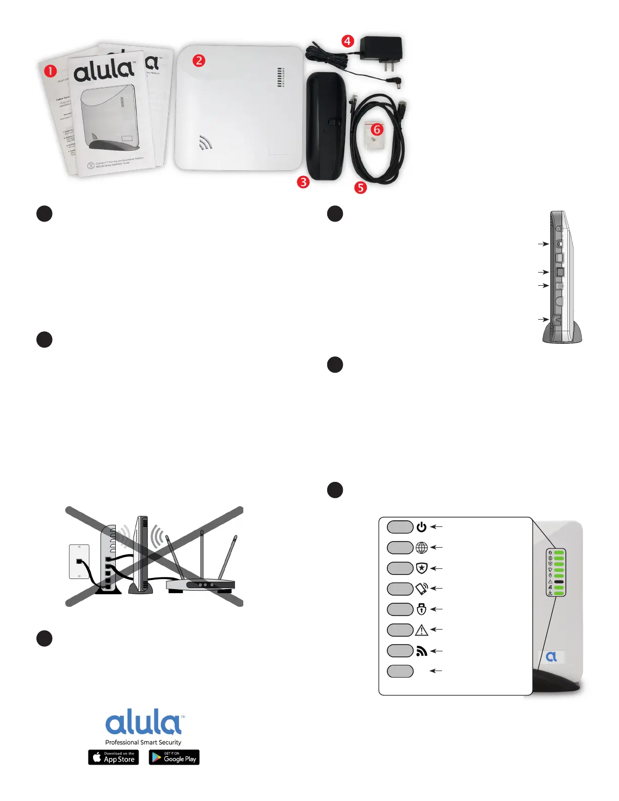
IN THE BOX
1. Installaon references
(for professionals)
2. Connect+ Hub
3. Table top base
4. 12V power supply
5. 6’ Ethernet cable
6. Cover screws
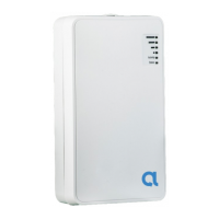
4
Power up the panel by
inserng the power supply barrel
into the power jack on the side of
Connect+. Route the power cable
under the strain relief peg (Figure
C). In the U.S.A., use the outlet
cover plate screw to fasten the
power supply to the wall outlet.
Ensure the 110V wall outlet is
unswitched, with constant power.
5
Connect the panel to the Internet by wiring
its Ethernet port to the home router. Alternately, if
you ordered your Connect+ with a Wi-Fi expansion
card, we have already installed it - using the Wi-Fi
approach requires enrollment into the home Wi-Fi
router. Hold the Enroll/WPS buon on Connect+
unl it beeps twice and then press the WPS buon
on your Wi-Fi router.
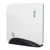
6
Conrm the top 5 LED’s on Connect+ are green
before placing your sensors (Figure D).
Figure A
POTENTIAL FOR INTERFERENCE
Figure B
Enroll/WPS
Ethernet Port
Power Jack
Power Strain
Relief
Figure C
Connections
Power
Pulsing - AC power connected
O - AC power is removed
Network Connecvity
On - Connected
O - No Connecon
Central Staon Connecvity
On - Connected
O - No Connecon
Alula Plaorm Connecvity
On - Connected
O - No Connecon
Arming Status*
Green - Disarmed
Red - Armed
Trouble
On - System trouble detected
O - No system trouble
RF Acvity
Flickering - Receiving sensor
data
System Firmware Update LED
On - No update needed
Blinking - Update in progress
O - No connecon
Figure D
 Loading...