EasyManua.ls Logo

Alvin Ensign User Manual

Alvin Ensign
4 pages
To Next Page IconTo Next Page
Page #1 background imageLoading...
Page #1 background image
Ensign Table
Tools Required: Phillips screwdriver, drill with
1
/16" bit, measuring tape, pencil (not included)
Assembly Instructions
Parts Included:
Warning: Do not cut restraining cord until after reading instructions
This table is spring-loaded and might cause bodily harm if assembled incorrectly. Remove
contents carefully from carton but do not cut table restraining cord until reading the assembly
instructions fully and taking necessary precautions as described below.
With the carton in the upright position, remove the table
frame
(
A
)
and feet/hardware box as shown in Figure 1. Do
not cut restraining cord yet and do not release brake lever yet.
1 2
A
1pc Table
Frame
C
4pcs
Foot Bolts
D
4pcs
Washers
E 4pcs
Tabletop Screws
F 1pc
Wrench
G
1pc Allen Wrench 5mm
1pc Allen Wrench 10mm
Table Assembly
Figure 1 Figure 2
x2
B
C
x4
x4
D
A
1
©2012 ALVIN & COMPANY, INC.
Attach feet
(
B
)
using foot bolts
(
C
)
and washers
(
D
)
provided. Be sure that the long ends of feet extend
toward the front of the table, as shown in Figure 2.
Tighten bolts very securely.
Front of
table
Long ends of
feet on front
side of table
Do not cut
restraining
cord yet
Do not
release
brake
lever yet
B
2pcs
Feet
H Spring
Tension Bolt
Question and Answer IconNeed help?

Do you have a question about the Alvin Ensign and is the answer not in the manual?

Alvin Ensign Specifications

General IconGeneral
BrandAlvin
ModelEnsign
CategoryIndoor Furnishing
LanguageEnglish

Summary

Table Assembly

Initial Unpacking and Safety Warnings

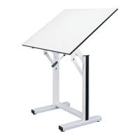
Remove table frame and hardware from carton, heed safety warnings regarding restraining cord and brake lever.

Attaching the Feet

Attach feet (B) to the table frame (A) using foot bolts (C) and washers (D).

Cutting Restraining Cord and Releasing Brake

Safely cut the restraining cord and release the brake lever to control the table's spring-loaded movement.

Attaching the Tabletop

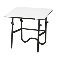
Secure the tabletop to the frame supports using tabletop screws, ensuring proper alignment.

Table Adjustments

Lift-Strength Adjustment

Adjust the lift control spring to ensure the tabletop rises gently and smoothly.

Tilt-Strength Adjustment

Adjust the tilt control spring for gentle and complete tilting of the tabletop.

Brake Control Adjustment

Increasing Braking Strength

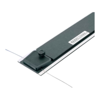
Adjust nuts to ensure the brake lever holds the tabletop firmly at any height or tilt position.

Related product manuals