IS-300CA INVERTER POWER SUPPLY
990-418 C-1
APPENDIX C
SYSTEM TIMING
Input and Output Timing Signals
The following illustrations show the timing signals for different functions of the Power Supply.
Start Signal Input
Weld sequence operation varies by the setting of
START SIG. MODE on the Mode Select screen.
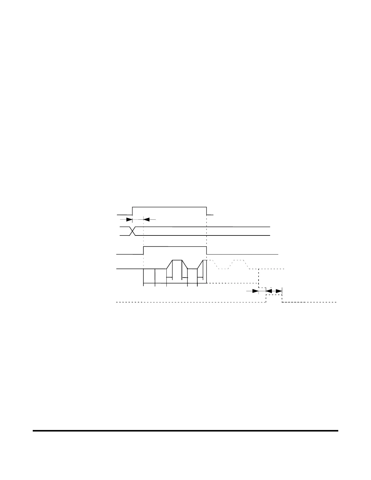
Maintained Mode
If the 2ND STAGE signal stops halfway through the welding sequence (from the beginning of initial
squeeze delay time through the end of hold time), the welding sequence will halt at that point.
Note that the END signal depends on the END SIG.MODE setting.
A
2ND STAGE
(1,2,4,8,16
32,64,128,P)
A: DELAY START SET
B
C
END si
nal output
no output if the weldin
sequence is halted
Schedule
selection
Weldin
sequence
B: Monitored value
ud
ment
time
C: END si
nal output
time
alve output
SOL1 or SOL2
SQD SQZ
UUD
WE1 CO1
Start Signal Input in Maintained Mode
(depends on the END SIG.MODE setting if
the welding sequence is halted)


 To Next Page
 Loading...
