APPENDIX C: SYSTEM TIMING
IS-300CA INVERTER POWER SUPPLY
C-10 990-418
VALVE MODE- specific difference in sequence
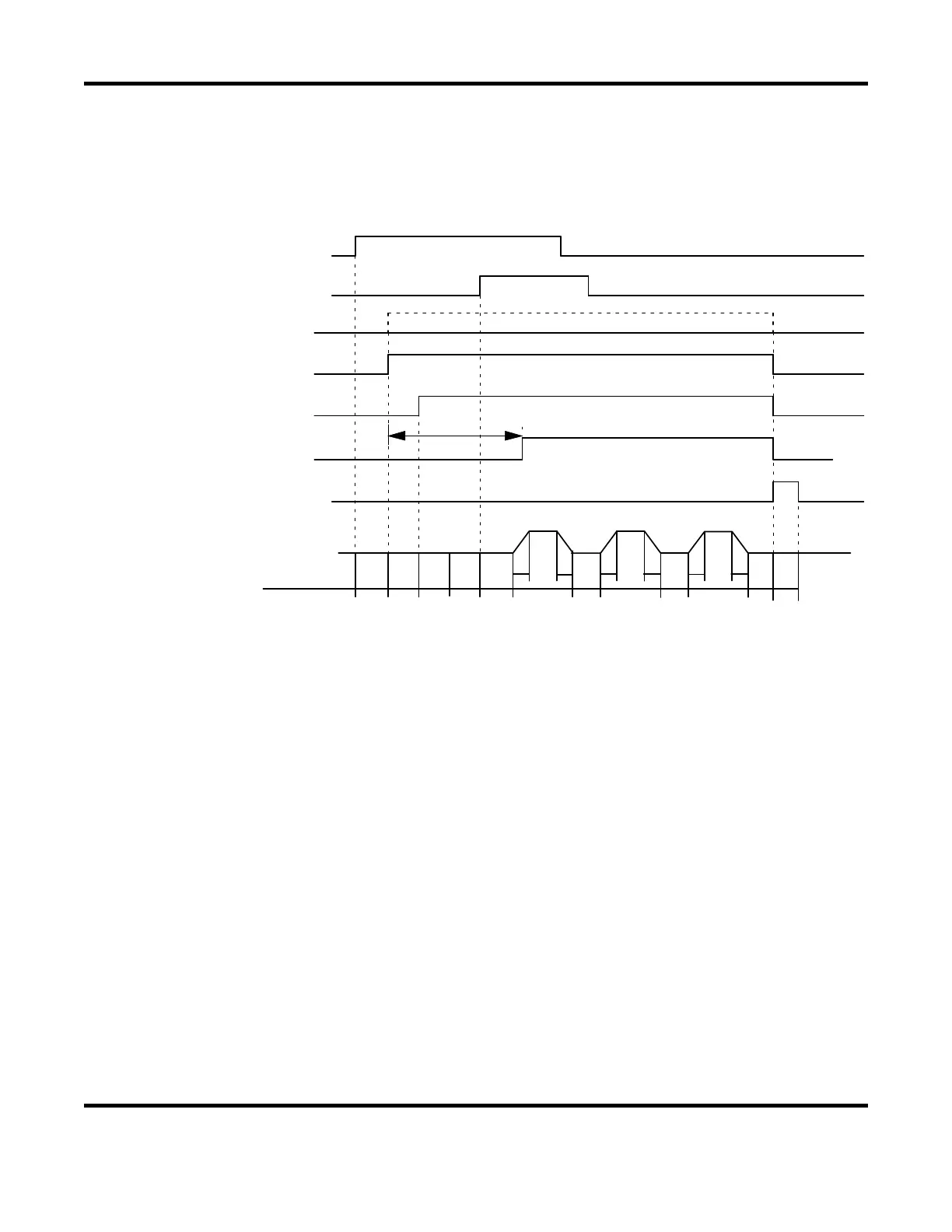
When VALVE MODE is changed to “2 VALVE” from “1 VALVE”, two valve signals (SOL1
and SOL2) are output in a sequence. In this case, the settable VALVE No. is 1 or 2.
UU
D
D
WE1 WE2
U
D
HOCO1
CO2
WE3
SQD
SQZ
TWT1 T1 T2
RELAY SW(Note 1)
SOL1 (No te 2 )
SOL2 (No te 2 )
FORGE VALVE (No te 3 )
e ld ing sequence
1ST STAGE
2ND STAGE
END
FORGE DELAY
(Note 1) The RELAY SW signal is not output when VALVE# is set to “1”. It is output from
SQD to HOLD only when VALVE# is set to “2”.
(Note 2) When VALVE# is set to “1”, the output signal No. of SOL1 is 36 and that of SOL2
is 37 on the 39-pin terminal strip. When VALVE# is set to “2”, the output signal
No. of SOL1 is 2 (EX SOL1) and that of SOL2 is 3(EX SOL2) on the 25-pin D-Sub
connector.
(Note 3) The output signal No. of FORGE VALVE is 4 (EX SOL3) when VALVE# is set to
“1”, and 5(EX SOL4) on the 25-pin D-Sub connector when VALVE# is set to “2”.


 To Next Page
 Loading...
