APPENDIX C: SYSTEM TIMING
IS-300CA INVERTER POWER SUPPLY
990-418 C-11
The timing charts below are for IS-300CA Advanced ONLY
CHAINING Function
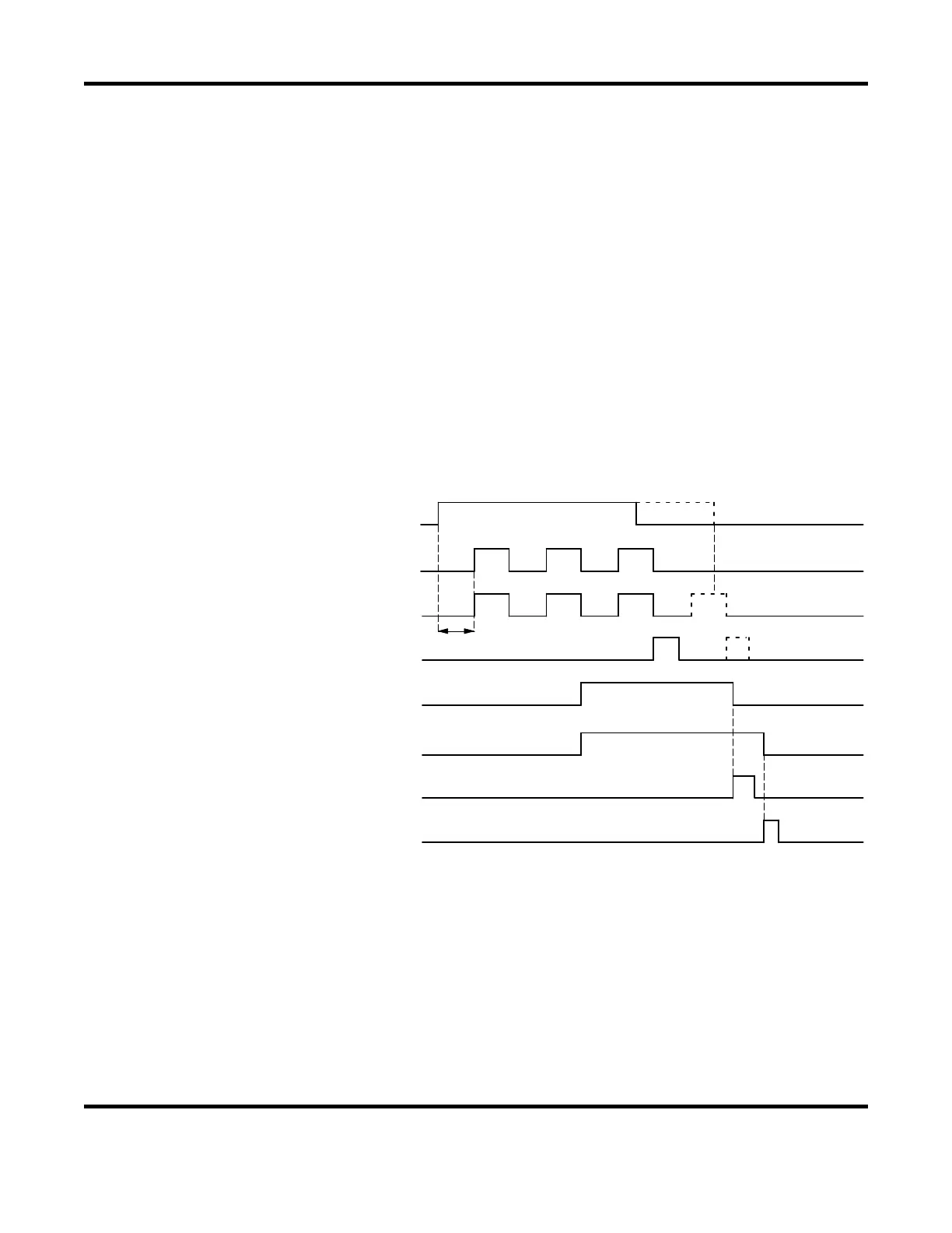
This function can call up welding multiple SCHEDULEs in order to perform them while the
1ST STAGE signal and the 2ND STAGE signal are input.
The SCHEDULE used in the chaining function is set in CHAINING on the FORCE SETUP &
MONITOR screen. For details, see Chapter 3, Section III, Force Setup & Monitor Screen.
Even if start is maintained, the sequence executes the final SCHEDULE and ends.
[Example] At 1-stage start operation
(For 2-stage start, the start method is different, but the operation after start is the same.)
In this example, the CHAINING settings for SCHEDULE1, 2, 5, and 6 are ON, and those for
other SCHEDULEs are OFF.
Since the 2ND STAGE signal is OFF when the sequence of SCHEDULE5 ends,
SCHEDULE6 is not executed.
Next, when the 2ND STAGE signal is input, the sequence starts from the first SCHEDULE1.
T1
SCH 1
SCH 2 SCH 5
OFF1 OFF2
T2
SCH 6
VALVE OUTPUT
END ( o u t )
ERROR ( o u t )
(When fau l t occu r . )
STEP END (ou t )
(When s teps comp le ted . )
ERROR RESET ( i n )
STEP RESET ( in )
(N o t e 1 )
We ld ing sequence
T1 : T ime se t by [DELAY START SET ]
OFF1 : OFF t ime se t by [SCHEDULE1 ]
OFF2 : OFF t ime se t by [SCHEDULE2 ]
1ST/2ND STAGE ( in )
T2 : Durat ion of END output s igna l
(Note 1) When the VALVE MODE setting is 1 VALVE, the valve selected from EXSOL1
to 4 is output.


 To Next Page
 Loading...
