APPENDIX E: EtherNet/IP
TM
COMMUNICATIONS
IS-300CR INVERTER POWER SUPPLY
E-42 990-418
Section VII. Bus Controller Diagnostic Status and Wiring
Diagrams
The X20BC0088 bus controller makes it possible to connect the X20 I/O modules to the Allen Bradley
®
PLC via EtherNet/IP
TM
. Once the bus controller is properly configured and powered up, it should
automatically listen for an active (master) scanner connection. When the Allen Bradley
®
PLC is
commanded to go ONLINE in run mode, it will try to connect to the bus controller with the assigned IP
address. If the connection between the Allen Bradley
®
PLC and bus controller is established, the LED
status indicators on the X20BC0088 should display as follows:
• Mod Status – Green and stays ON
• Net Status – Green and stays ON
• L/A IF1 – Green and continuously blinks
Or of the bus controller is connected via L/A IF2, then:
• L/A IF2 – Green and continuously blinks
If the Mod status or Net Status LED indicator shows anything other than the Green/On, the bus
controller either has not been properly configured or there is some communication issue. Refer to the
X20BC0088 LED Status Indicator section below for the descriptions of each status indicator.
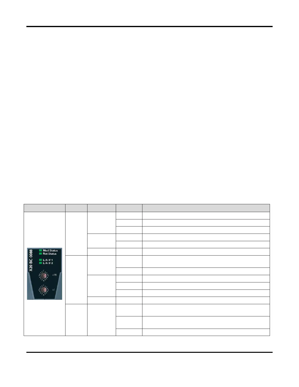
X20BC0088 LED Status Indicators
Mod
status
1
Green
On Indicates that there is at least one client connection
Blinking Bus controller not yet configured
Flickering HTTP file upload (firmware or configuration file)
Red
On Major unrecoverable fault
Blinking Major recoverable fault
Green/Red Blinking Initialization / Self-test
Net
status
1
Green
On
Indicates at least one established active scanner (master)
connection
Blinking Indicates no established active scanner (master) connection
Red
Off Indicates no IP address has been assigned
On Indicates an IP address has been used more than once
Blinking Indicates a timeout on at least one connection
Green/Red Blinking Initialization / Self-test
L/A IFx Green
Blinking
Ethernet activity taking place on the RJ45 port (IF1, IF2)
indicated by the respective LED
On
Indicates an established connection (link), but no
communication is taking place.
Off Indicates that no physical Ethernet connection exists
1. The “Mod Status” and “Net Status” LED’s are green/red dual LED’s
 Loading...