CHAPTER 3: USING PROGRAMMING FUNCTIONS
IS-300CA INVERTER POWER SUPPLY
3-14 990-418
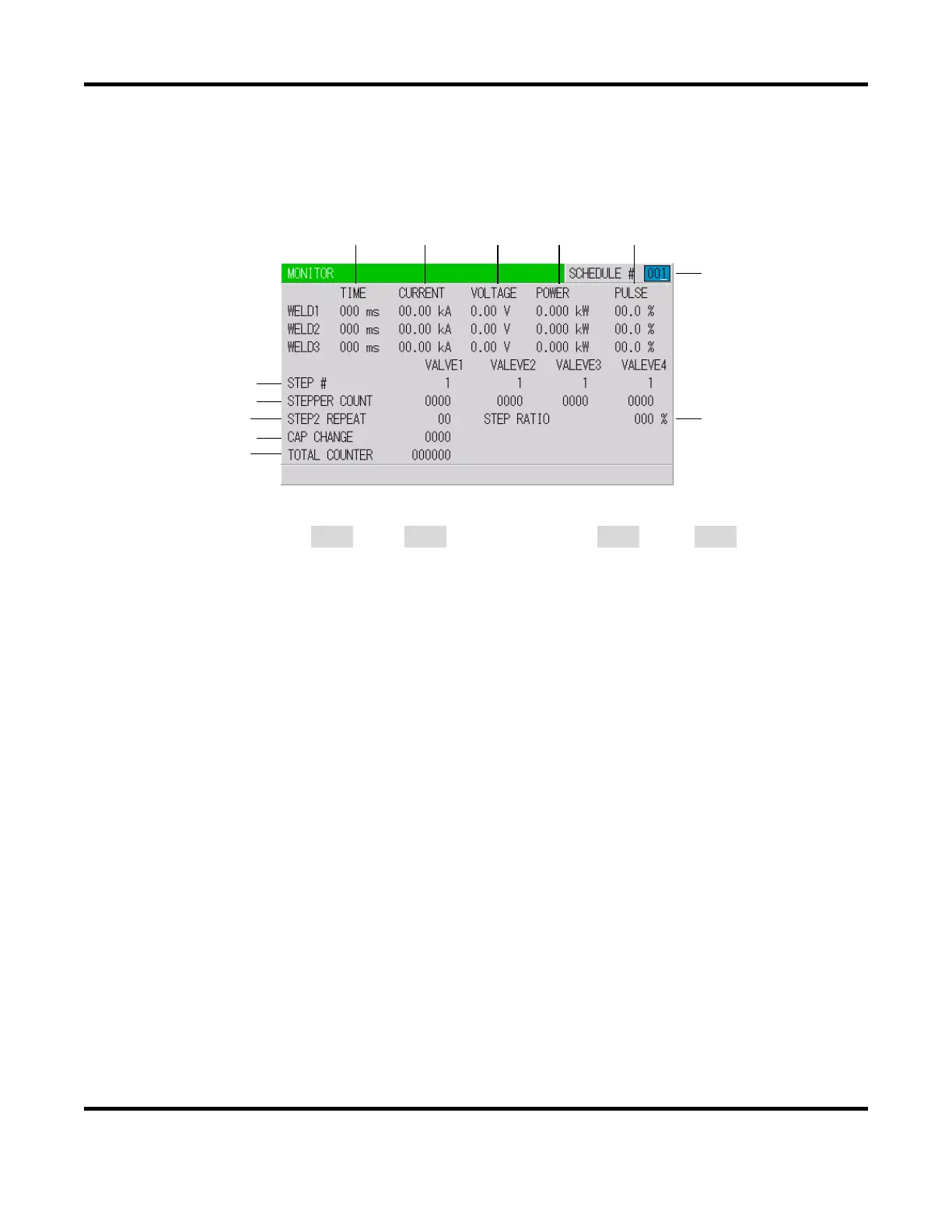
4. MONITOR Screen
In this screen, you can confirm the operational conditions during welding. Monitored data is
displayed for each SCHEDULE.
(b) (c) (d) (e) (f)
NOTE: The screen shows the settings for 10 kA or 05 kA range. In 20 kA, 40 kA, or 80 kA
range, CURRENT is 000.0 kA to 999.9 kA and POWER is 000.0 kW to 999.9 kW.
a. SCHEDULE #
Set the No. of the SCHEDULE to monitor. The measured values (welding current, voltage, etc.)
for welding within that SCHEDULE are displayed. The Power Supply stores the latest measured
values of each SCHEDULE number. The stored measurement values are not erased even when
the power is turned off, and thus can be checked for the next job.
b. TIME
The lengths of periods during which current was supplied in the course of WELD1, WELD2 and
WELD3 operations are displayed. The latest measured value welded with the displayed
SCHEDULE No. is displayed. As units of time, ms and CYC may be selected. Either unit can
be selected via the
MODE SELECT screen.
c. CURRENT
The current during which current was supplied in the course of WELD1, WELD2 and WELD3
operations are displayed. The latest measured value welded with the displayed SCHEDULE
No. is displayed.
d. VOLTAGE
The voltage during which current was supplied in the course of WELD1, WELD2 and WELD3
operations are displayed. To display the voltage, you need to measure the secondary voltage by
connecting the voltage detecting cable. The latest measured value welded with the displayed
SCHEDULE No. is displayed.
(g)
(h)
(i)
(k)
(l)
(a)
(j)
 Loading...