CHAPTER 3: USING PROGRAMMING FUNCTIONS
IS-300CA INVERTER POWER SUPPLY
990-418 3-21
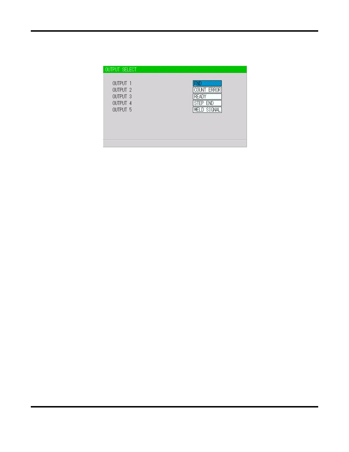
7. OUTPUT SELECT Screen
Sets the output signals OUT1 (Pin 28) to OUT5 (Pin 32) of the external output signals.
NOTE: This screen shows initial settings.
Pressing the +ON key switches the signal in the following order (in the reverse direction when
pressing -OFF key):
END (end signal) COUNT ERROR (count error signal) READY (ready signal)
STEP END (step end signal) WELD SIGNAL (welding timing signal)
GOOD (normal signal) COUNT UP (count up signal)
OUT I (OUT I timing output) OUT II (OUT II timing output)
For output timings of END, WELD SIGNAL, GOOD, OUT I, and OUT II, see the Timing Chart.
 Loading...