EasyManua.ls Logo

Amada MacGregor DC 13-T Series User Manual

Default Icon
25 pages
To Next Page IconTo Next Page
Page #1 background imageLoading...
Page #1 background image
961-00060 rev9
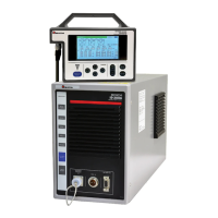
DC Spot Welding Power Supply
DCxx13-T and M31xx-T
Resistance Welders
HARDWARE MANUAL

Questions and Answers:

Amada MacGregor DC 13-T Series Specifications

General IconGeneral
BrandAmada
ModelMacGregor DC 13-T Series
CategoryWelding Accessories
LanguageEnglish

Summary

Annex

Safety regulations

Safety regulations for resistance welding operations.

General references on resistance welding

Provides general references and information related to resistance welding.

Contact addresses

Lists contact information and addresses for support and inquiries.

General Information

Safety First

Emphasizes safety as the primary rule for operating the equipment.

Hazards and Precautions

Details potential hazards (mechanical, electrical, thermal, crushing) and necessary precautions.

Environmental Restrictions

Notes on operating environment, including conductive dust and EMC considerations.

Technical Description

Introduction

Introduces the MacGregor resistance welding power source and its purpose.

Technical Specification Reference

Refers to the associated hardware manual for detailed technical specifications.

Commissioning

Electrical Connections

Guidelines for connecting the unit to mains power, including single and three-phase.

Preparation and Installation: DCxx13 Front Panel

DCxx13 Front Panel Overview

Details the front panel components and layout for DCxx13 models.

Preparation and Installation: M31 Range Front Panel

M31 Range Front Panel Overview

Illustrates and describes the front panel features of M31 range welders.

Preparation and Installation: DCxx13 Rear Connections

DCxx13 Rear Panel Connections

Explains the rear panel connectors and their functions for DCxx13 units.

Preparation and Installation: DC6013T/DC1013T Rear Connections

DC6013T/DC1013T Rear Panel Connections

Details rear panel connections for DC6013T and DC1013T models.

Preparation and Installation: M31 Range Rear Connections

M31 Range Rear Panel Connections

Describes the rear panel connections for the M31 range welders.

Rear Panel Connections: Standard IO Interface

Standard IO Isolated Interface

Details standard input/output connections via a 37-pin D-type connector.

Standard Outputs

Lists and describes the standard outputs available at the PLC interface socket.

Rear Panel Connections: Standard IO Details

Standard Inputs

Lists and describes the standard inputs available at the PLC interface socket.

Standard IO Default Configuration

Shows the default mapping of standard outputs to specific functions.

Rear Panel Connections: DS Option

DS Option Configuration

Explains the input/output configurations for the DS option.

Rear Panel Connections: BCD and Optional IO

BCD Option Configuration

Details the input/output mapping for the BCD option.

Optional IO Isolated Interface

Describes the expanded input/output options via an optional 37-pin D-type socket.

Optional Outputs

Lists and describes the optional outputs available at the PLC interface.

Rear Panel Connections: Optional IO Details

Optional Inputs

Lists and describes the optional inputs available at the PLC interface.

Optional IO Default Configuration

Shows the default mapping of optional outputs to specific functions.

Rear Panel Connections: Optional BCD and Program Echo

Optional BCD Option Configuration

Details the BCD option configuration for optional outputs and inputs.

Program Echo Configuration

Explains the program echo feature and its BCD output mapping.

Rear Panel Connections: Communication Ports

Isolated RS232 Communications

Describes the optically isolated RS232 communication port and its pinout.

PC Port Connection Guide

Guides on interfacing the machine with PC serial ports (9-pin and 25-pin).

15-way Trigger/Fault D-type Connector

Details the signals and indicators available on the 15-way Trigger/Fault D-type connector.

Rear Panel Connections: Ancillary Functions

Voltage Sensing and Stop Functionality

Explains the function of the STOP link and voltage sensing terminals.

Isolated Analogue Outputs

Describes the optional optically isolated analogue outputs for monitoring process parameters.

Ethernet, USB, and FS1 Fuse

Covers the Ethernet, USB ports, and the FS1 fuse protection.

Rear Panel Connections: Quick Connect

Quick Connection Strip

Details the quick connection strip for solenoid and trigger connections.

Fault Codes and Warnings

Fault Code Descriptions

Lists and describes fault codes with their corresponding remedies.

Screen Warning Messages

Details warning messages displayed on the screen and their remedies.

Trouble Shooting Guide

Typical Process Variables

Lists common process variables that can affect welding performance.

Troubleshooting Checklist

Provides a step-by-step checklist for diagnosing and resolving issues.

Related product manuals