11
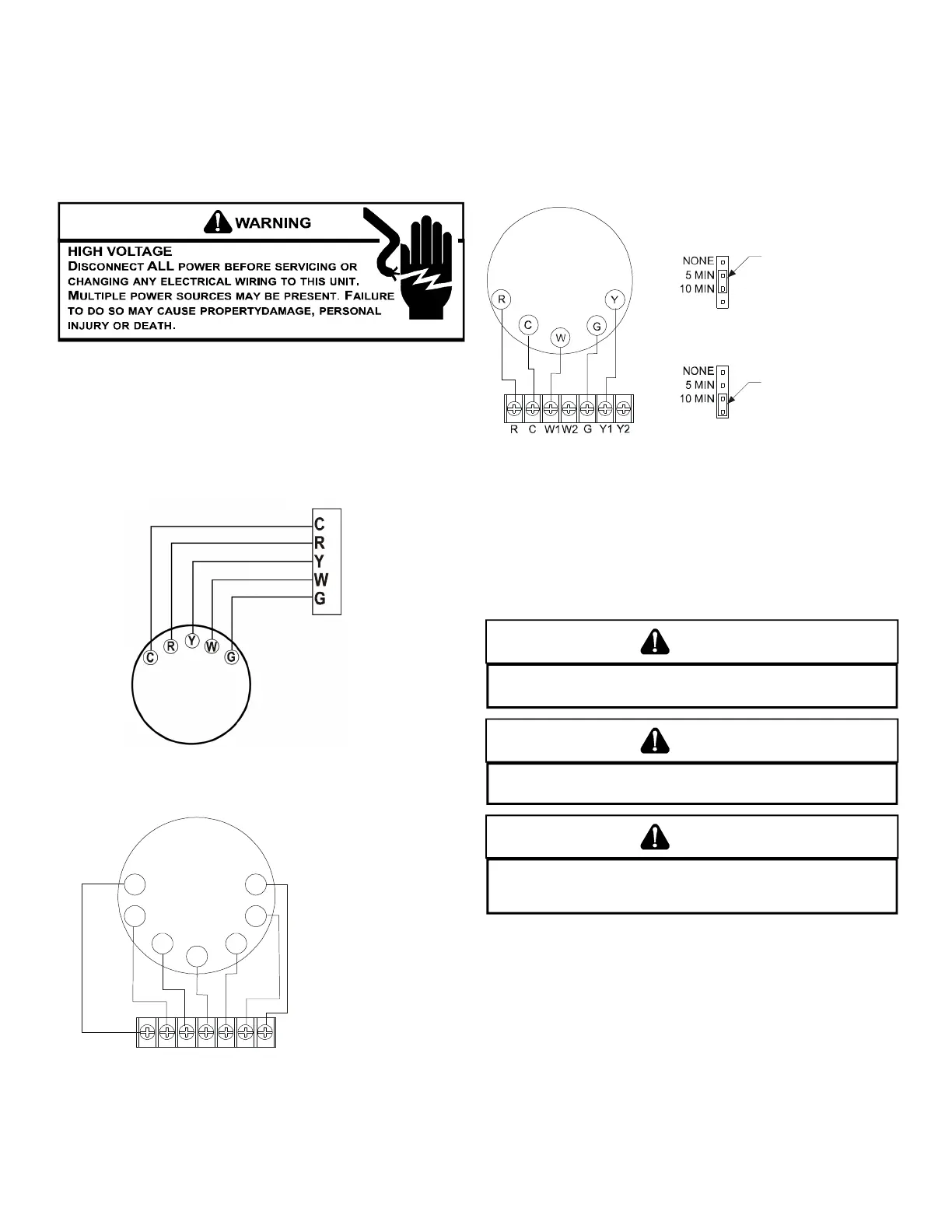
SINGLE STAGE THERMOSTAT - TWO-STAGE MODELS
To use a single stage thermostat, move jumper located to the
left of the terminal strip labeled “Stage Delay” from NONE to
“5” or “10” minutes. This selection will cause the control to
run on low stage for the selected time (5 or 10 minutes) then
shift to HIGH STAGE. This option controls both cooling and
heating modes. If the jumper is not moved, only low-stage
cool and low-stage heat will operate.
PERIOD WITH
POSITION
PERIOD WITH
JUMPER IN THIS
POSITION
Two-Stage Heating (timed) and Two-Stage Cooling (timed)
with Single Stage Thermostat Diagram
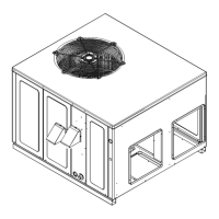
Refer to the unit wiring diagram for electrical connections.
When installed, the unit must be electrically grounded in
accordance with local codes or in the absence of local codes,
with the National Electrical Code, ANSI/NFPA No. 70, and/or
the CSA C22.1 Electrical Code. Ensure low voltage
connections are waterproof.
WARNING
T
O AVOID THE RISK OF ELECTRICAL SHOCK, WIRING TO THE UNIT MUST BE
POLARIZED AND GROUNDED.
CAUTION
T
O AVOID PROPERTY DAMAGE OR PERSONAL INJURY DUE TO FIRE, USE
ONLY COPPER CONDUCTORS.
CAUTION
T
O PREVENT IMPROPER AND DANGEROUS OPERATION DUE TO WIRING ERRORS,
LABEL ALL WIRES PRIOR TO DISCONNECTION WHEN SERVICING CONTROLS.
V
ERIFY PROPER OPERATION AFTER SERVICING.
For unit protection, use a time delay fuse or HACR circuit
breaker that is in excess of the circuit ampacity, but less than
or equal to the maximum overcurrent protection device. DO
NOT EXCEED THE MAXIMUM OVERCURRENT DEVICE SIZE
SHOWN ON UNIT DATA PLATE.
All line voltage connections must be made through
weatherproof fittings. All exterior power supply and ground
wiring must be in approved weatherproof conduit. Low voltage
wiring from the unit control panel to the thermostat requires
coded cable. See below for ground level and rooftop wiring.
etc. Consult the Instruction Sheet packaged with thermostat
for mounting instructions.
Five ton models have two stages of heating and two stages of
mechanical cooling. Units which have economizers may use
thermostats with two or three stages of cooling.
All other units have one stage of heating and one stage of
mechanical cooling. Units which have economizers may use
thermostats with one or two stages of cooling.
The units are designed for operation on 60 hertz current and
at voltages as shown on the rating plate. All internal wiring in
the unit is complete. It is necessary to bring in the power
supply to the contactor as shown on the unit wiring diagram
which is supplied with each unit. 24 volt wiring must be
connected between the unit control panel and the room
thermostat.
Thermostat Wiring - Single Stage Models
Uni
Single Stage Heating & Cooling Thermostat Diagram
Thermostat Wiring - Two Stage Models
R
Y2
CY1
W1
G
W2
Control Module
Thermostat
Two-Stage Heating
with
Two-Stage Cooling
(
Two-Stage Heating with Two-Stage Cooling
Thermostat Diagram
 Loading...