13
The supply duct from the unit through a wall may be installed
without clearance. However, minimum unit clearances as
shown in the appendix must be maintained. The supply duct
should be provided with an access panel large enough to
inspect the air chamber downstream of the heat exchanger. A
cover should be tightly attached to prevent air leaks.
For duct flange dimensions on the unit refer to the Unit
Dimension illustration in the appendix.
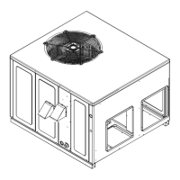
For down-discharge applications, the ductwork should be
attached to the roof curb prior to installing the unit. Ductwork
dimensions are shown in the roof curb installation manual.
If desired, supply and return duct connections to the unit may
be made with flexible connections to reduce possible unit
operating sound transmission.
FILTERS
CAUTION
T
O PREVENT PROPERTY DAMAGE DUE TO FIRE AND LOSS OF
EQUIPMENT EFFICIENCY OR EQUIPMENT DAMAGE DUE TO DUST AND LINT
BUILD UP ON INTERNAL PARTS, NEVER OPERATE UNIT WITHOUT AN AIR
FILTER INSTALLED IN THE RETURN AIR SYSTEM.
Even though a return air filter is not supplied with this unit,
there must be a means of filtering all return air. All units may
be externally filtered.
Refer to the unit filter size chart in the appendix for filter size
information.
Filters installed external to the unit should be sized in
accordance with their manufacturer recommendations. A
throwaway filter must be sized for a maximum face velocity of
300 feet per minute.
Filter Installation
Important: When installing a filter, the air flow arrows on the
filter must point toward the circulator blower.
VENTING
NOTE: Venting is self-contained. Do not modify or block.
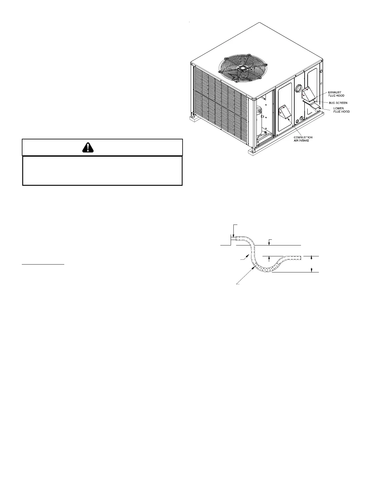
FLUE H OOD I NSTALLATION
Install the exhaust flue hood and combustion air intake hood
prior to operation of the unit.
To install the flue hood cover, please refer to the installation
instructions, included in the flue hood assembly package
located in the blower compartment.
Flue Hood and Bug Screen Installation
CONDENSATE DRAIN
CONDENSATE DRAIN C ONNECTION
A 3/4” NPT drain connection is supplied for condensate piping. An
external trap must be installed for proper condensate drainage.
NOTE: Maximum torque is 10 in-lbs.
DRAIN
CONNECTION
UNIT 2" MINIMUM
LEXIBLE
UBING-HOSE
R PIPE
3" MINIMU
A POSITIVE LIQUID
Drain Connection
NORMAL SEQUENCES OF OPERATION
HEATING
This unit is equipped with an ignition control that automatically
lights the main burner. DO NOT attempt to light the main
burners by any other method.
1. Thermostat calls for heat.
2. The induced draft blower energizes for a 15-second pre-
purge.
3. The spark igniter and gas valve energizes for 7 seconds.
NOTE: The igniter produces a very intense electrical spark
that ignites the gas.
4. Main burners light and control detects presence of flame.
5. The 30-second HEAT FAN ON delay time begins after the
main burners light.
6. The unit delivers heat to the conditioned space until the
thermostat is satisfied.
Two-Stage Models:
If the call is for low stage heat, the induced draft blower
switches to low speed and the high stage gas valve closes
 Loading...