3
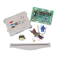
GY22
BK37
BK37
LIN E 1
HEATER 1
HEATER 2
LINE 2
COMPRESSOR
24VAC~ TRANSFORMER
12VA CLASS 2 ONLY
GY21
TRANSFORMER
LINE
LOAD
COM
265
230
Figure 4
16. Thermistor Temperature Sensors Installation
A. It is recommended that the Indoor Discharge
Thermistor (with the YELLOW wires) be installed
but it is optional. If you choose not to install this
sensor, the green status light will remain illuminated
continuously. For status light functionality,
the YELLOW thermistor MUST be installed.
Instructions are as follows:
A1. Carefully cut and remove the gasket on the left
and right sides of discharge screen. Remove
the two (2) 5/16” screws holding the indoor
exhaust screen above the indoor coil. Remove
the indoor exhaust screen.
Remove the two (2) 1/4” screws connecting the
heater panel to the evaporator coil.
Remove the two (2) screws mounting the air
bae to the top of the heater panel and remove
and discard the air bae.
A2. Install the new air bae. Route the yellow
thermistor probe from right to left through the
wiring tube enclosure. Mount the black tip of
the yellow thermistor probe in the plastic clip
provided. Hold the plastic clamp in place and
secure the clamp to the left end of heater panel
using one of the original screws. Replace the
screw on the right end of the air bae being
careful not to damage the wiring insulation on
the probe.
YELLOW
THERMISTOR
PLASTIC CLAMP
CLAMP END OF
THERMISTOR
SECURELY
WIRE ENCLOSURE
ROUTE THERMISTOR
THROUGH TUBE ON
BLOWER EXTENSION
Figure 5
A3. Replace the heater panel, routing the yellow wire
around the right end of the heater panel and into the
control panel pulling snug to prevent the wire from
being entangled in the blower wheel or being visible
from above. Replace the two screws mounting the
heater panel to the evaporator coil.
A4. Replace the exhaust grille and two mounting screws.
A5. Connect the yellow wire using the plug-on connector
to the new board on the IDT (yellow) terminals.
B. If the existing Indoor Ambient Thermistor (with the
BLACK wires) was connected to the board by a plug-
on connector, reconnect it to the new board on the IAT
(black) terminals. If the existing Indoor Coil Thermistor
was soldered to the previous board, install the new black
thermistor per Figure 6 and connect as above.
Clip is designed to be pushed
into the coil between
the aluminum fins
and attach over
two (2) screws.
Figure 6
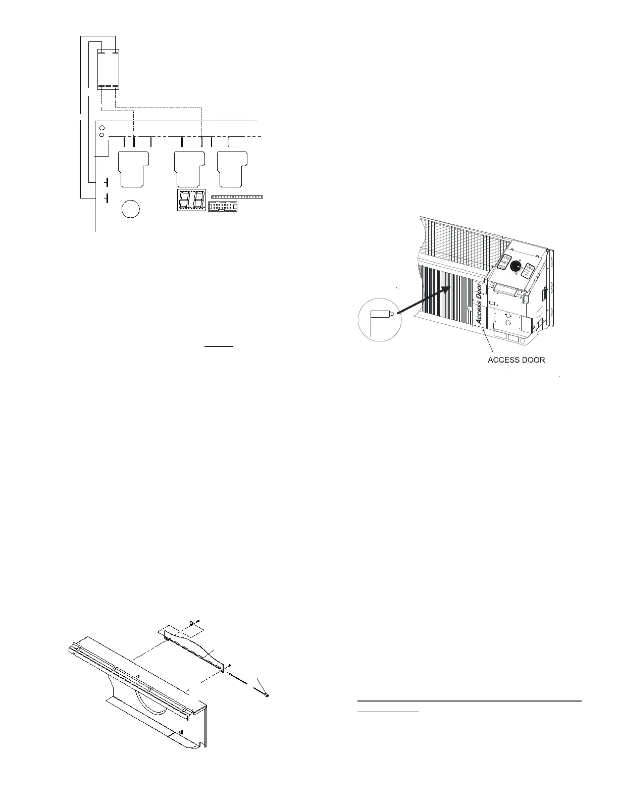
C. If the existing Indoor Coil Thermistor (with the RED wires)
was connected to the board by a plug-on connector,
reconnect it to the new board on the ICT (red) terminals.
If the previous board used indoor coil bi-metals, remove
and discard the bi-metal devices. The access door will
need to be removed on the indoor coil to gain access to
the bi-metal. See Figure 6. The Indoor Coil Thermistor
will need to clip on the vertical section of the 90-degree
bend of the inlet line to the indoor coil. See Figure 7.
Connect the Indoor Coil Thermistor to the board as
noted above.
D. If the existing Outdoor Coil Thermistor (with the BLUE
wires) was connected to the board by a plug-on
connector, reconnect it to the new board on the OCT
(blue) terminals. If the previous board used indoor coil
bi-metals, remove and discard the bi-metal devices. The
Indoor Coil Thermistor will need to clip on the crossover
tube shown in Figure 8. There will be two clips supplied
in the kit for the Blue Thermistor. One clip as supplied
on the sensor will t 5/16” tubing used on the bent coil,
and an additional clip (loose in the bag) will t 3/8” tubing
used on the at slab coil. If you have a slab coil, you
will need to remove the 5/16” clip from the sensor and
replace it with the 3/8” tube clip. Connect the Outdoor
Coil Thermistor to the board as noted above. Outdoor
Coil Thermistors are only used on Heat Pump models;
DO NOT INSTALL THIS SENSOR IF THE UNIT IS NOT
A HEAT PUMP.
 Loading...