4
Figure 7
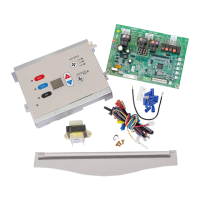
INDOOR COIL THERMISTOR - RED
All Units
Connect to ICT on Control Board
Cross over tube
for 9,12 and 15k
or center tube for
7,000 BTU
Figure 8
17. The control board cover is now ready to be installed. The
ribbon for the touch pad will need to be connected to the
control board. Take caution not to bend or fold the
ribbon.
(See Figure 10 for ribbon connection).
Ensure that no wires are pinched or caught between the
cover and the panel and then reinstall the screws removed
in Step 5.
If a remote thermostat or any low voltage accessory is
being used connect the low voltage pin connector to low
voltage terminal strip.
If replacing a previous version board you will need to use
the 10 pin connector supplied with the board for low voltage
accessories. Wires supplied with this kit have terminal
ends on the wires. Insert the terminal end into the correctly
labeled slot, push in and it will lock in place. After loading
pin connector use the wire nuts supplied with the kit to wire
nut the new wires onto the existing wires supplied for low
voltage accessories. See Figure 9 on page 5.
18. Set the master switch to ON. Restore electrical power and
verify unit functionality.
19. Replace the front in reverse order as removed in Steps 2
and 3.
 Loading...