EasyManua.ls Logo

Amana RSKP0014 - User Manual

Amana RSKP0014
20 pages
Print Icon
To Next Page IconTo Next Page
Loading...
ATTENTION INSTALLING PERSONNEL
As a professional installer you have an obligation to know
the product better than the customer. This includes all safety
precautions and related items.
Prior to actual installation, thoroughly familiarize yourself with this
Instruction Manual. Pay special attention to all safety warnings.
Often during installation or repair it is possible to place yourself
in a position which is more hazardous than when the unit is in
operation.
Remember, it is your responsibility to install the product safely
and to know it well enough to be able to instruct a customer in its
safe use.
Safety is a matter of common sense...a matter of thinking before
acting. Most dealers have a list of specic good safety practices...
follow them.
The precautions listed in this Installation Manual are intended as
supplemental to existing practices. However, if there is a direct
conict between existing practices and the content of this manual,
the precautions listed here take precedence.
RECOGNIZE THIS SYMBOL AS A SAFETY PRECAUTION
Only personnel that have been trained to install, adjust, service

manual should service the equipment. The manufacturer will not
be responsible for any injury or property damage arising from
improper service or service procedures. If you service this unit,
you assume responsibility for any injury or property damage
which may result. In addition, in jurisdictions that require one or

only licensed personnel should service the equipment.
Improper installation, adjustment, servicing or repair of the


without proper training may result in product damage, property
damage, personal injury or death.
WARNING
Cancer and Reproducve Harm -
www.P65Warnings.ca.gov
PROP 65 WARNING
FOR CALIFORNIA CONSUMERS
0140M00517-A
WARNING
DESCRIPTION
Control board installation procedures are described in detail in
these instructions. Read and follow these instructions carefully
before replacing the control board. Failure to do so may result in
control board damage.

Damage to the control board can occur from failure to disconnect
power supply or failure to set the master switch (located on the
control board) to OFF before removing the low voltage terminal
strip cover from an installed control board. Damage to this board
by not following these instructions is considered misuse and not
covered under either the standard unit warranty or any extended
service contract.

All warranty replaced boards must be returned to the parts source
from which they were purchased to insure proper warranty credit.
ELECTROSTATIC DISCHARGE (ESD)
PRECAUTIONS
Before removing the new control board from the static wrap, it
is very important to discharge any static electricity. Discharging
the static electricity can be accomplished by two methods: the
servicer can wear a ground strap or by touching the metal chassis
before replacing the board.
EXISTING BOARD REMOVAL PROCEDURE
1. Disconnect power to the unit by unplugging the power cord
at the wall outlet or subbase, or disconnect power at the fuse
box or circuit breaker.
19001 Kermier Rd., Waller, TX 77484
www.amana-ptac.com
IO-905B
01/2020


is a registered trademark of Maytag Corporation or its related companies and is used
under license to Goodman Company, L.P., Houston, TX, USA. All rights reserved.
© 2015 - 2016, 2020 Goodman Company, L.P.
Question and Answer IconNeed help?

Do you have a question about the Amana RSKP0014 and is the answer not in the manual?

Amana RSKP0014 Specifications

General IconGeneral
BrandAmana
ModelRSKP0014
CategoryControl Unit
LanguageEnglish

Summary

Installation Instructions

Attention Installing Personnel

General guidance and obligations for professional installers performing the installation.

Description and Safety

Overview of control board installation, high voltage, ESD, and general safety precautions.

Existing Board Removal Procedure

Initial steps for removing the old control board from the unit.

New Control Board Installation Procedures

Cabinet Front, Component, and Board Removal

Steps for removing front panels, components, wires, and the old control board.

Transformer and Board Installation

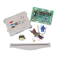
Mounting the external transformer, connecting wires, and installing the new control board.

Thermistor Installation and Connections

Installing and connecting various thermistor sensors to the control board.

Control Cover, Accessory Wiring, and Final Reassembly

Installing cover, connecting accessories, verifying power, and reattaching front panel.

Configuration Requirements

Critical Configuration Steps

Importance of setting feature codes for proper unit operation and functionality.

Heat Pump;Cooler and Cooling Capacity Configuration

Setting configuration codes C3 for unit type and 'dd' for cooling capacity.

Initial Board Programming

Entering and Navigating Configuration

Steps to enter configuration mode and select feature codes.

Exiting Configuration Mode

Procedure for saving settings and exiting the configuration menu.

Configuration Settings Chart

Interface, Fan, Model, and Cooling Settings

Configuration options for unit interface, fan operation, model prefix, and cooling.

Temperature, Occupancy, Delay, and Capacity Settings

Settings for temperature limits, occupancy, setbacks, capacity, and voltage.

Vent, Dehumidification, and Input Pin Settings

Configuration for smart vent, dehumidification, and input pin functions.

Diagnostic Maintenance & Status Report

Entering and Viewing Diagnostic Data

Steps to access and view active failures, operating temperatures, and past failure logs.

Diagnostic Codes

Operational, Thermistor, and Component Codes

Detailed breakdown of diagnostic codes for operation, sensors, and components.

Wiring Diagrams

Single Motor Wiring Diagrams

Electrical schematics for single motor configurations.

Single Motor Power Vent Door Wiring

Electrical schematic for single motor units with power vent doors.

Single Motor Condensate Pump Wiring

Electrical schematic for single motor units with condensate pumps.

Dual Motor Wiring Diagrams

Electrical schematics for dual motor configurations.

Motor Speed and Daughter Board Configuration

Tables for motor speed selection and daughter board DIP switch settings.

Dual Motor 2-Speed Relay Wiring

Electrical schematic for dual motor units with 2-speed relays.

Dual Motor Single Speed Condenser Fan Wiring

Electrical schematic for dual motor single speed condenser fan units.

Dual Motor DC Outdoor Motor Wiring

Electrical schematic for dual motor units with DC outdoor motors.

Dual Motor DC Indoor Motor Wiring

Electrical schematic for dual motor units with DC indoor motors.

Customer Feedback

Feedback Submission

Instructions and links for providing product comments and feedback.

Related product manuals