22
EN
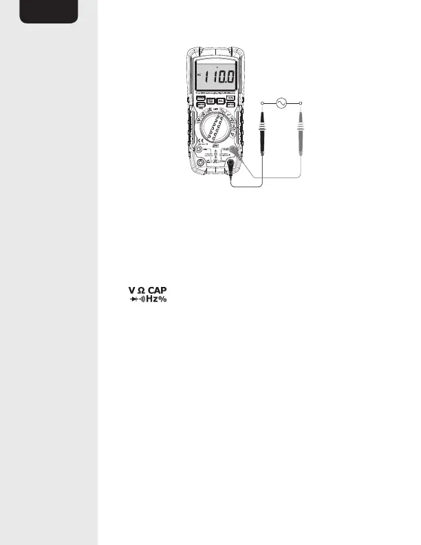
• Set the function switch (E) to the V~ Hz % VFD
position. “AC” will be indicated on the display.
• Insert the black connector lead (Q) into the
COM input jack (L).
• Insert the red connector lead (Q) into the
input jack (K).
• Connect the test probes (Q) in parallel to the
circuit under test.
• The stabilized value on the display (A) is read as
the actual reading.