18
To replace the injector
Remove burner head as on previous page.
Unscrew injector from its carrier using a
spanner on the hexagonal portion of its body.
When replacing ensure the injector is fully
tightened in its carrier. For correct injector size
see data badge on heater.
T
o replace gas safety control valve
(double solenoid and governor models S.I.T.,
Honeywell and Black/Teknigas).
Remove combustion chamber cover as on
previous page. Remove control housing cover
by removing the two dome headed fixing
screws. Remove burner head and the 2 screws
holding inlet gas connection supply support
plate. Disconnect the gas valve electrical
connection, marking each connection.
The gas valve and injector can now be
removed as an assembly. Using an approved
pipe joining compound on pipe threads
,
refit the pipe fittings onto the replacement
control valve. Replace the control valve into
the control housing (refit burner onto injector
holder before tightening inlet support plate
screws). Carry out commissioning, setting
the burner pressure to that indicated on
the data badge.
Note Insulated inline connectors are used
on Black/Teknigas control valve.
To replace the electronic
sequence controller
Swing open the safety control housing cover
by unscrewing two screws. Disconnect the
electrical connector on the side of the
electronic sequence controller. Unplug the
single grey high tension lead from the
electronic sequence controller. Remove the
two bolts securing the sequence controller to
the control housing door and replace the
sequence controller using the high tension
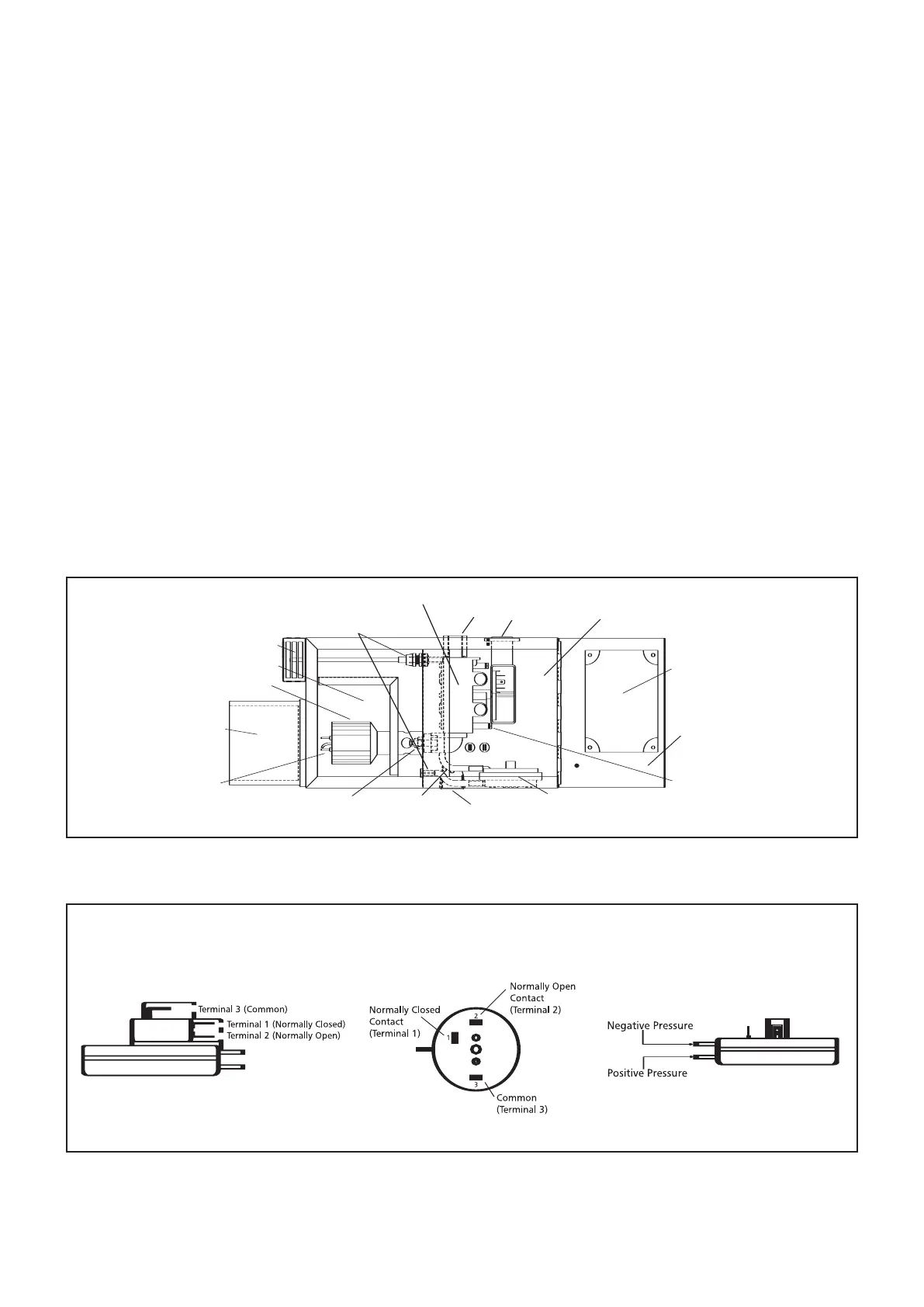
Gas supply
pipe
Gas safety control valve
3 pins main
inlet socket
S
afety control
housing
Electronic sequence
controller
Hinged lid
Gas pressure
test pipe
Vacuum
proving switch
Impulse line
Pressure sensing tube
Air intake guard
Combustion chamber
Burner head
Burner assembly
support casing
Electrode/igniter
assembly
Injector
3 pin fan
socket
Figure 15 Model AR burner assembly
Figure 16 S.I.T. vacuum proving switch
lead (grey) from the old controller unless its
insulation is damaged. When refitting the
pactrol sequence controller
, take care that the
rear flanges of the sequence controller are
correctly located underneath the retaining lip
in the door of the control housing (pactrol
P16DIA only). Refit the two bolts and electrical
connector into the sequence controller and
high tension leads into its connector.
To replace the vacuum proving switch
Disconnect the two silicon rubber tube
connections at the vacuum switch.
Disconnect the three push on connectors
from the vacuum switch. Remove the two
screws securing the vacuum switch and
slip the vacuum switch out of the control
housing. Refitting is a reversal of the above,
taking care to correctly reconnect the
three cables.
 Loading...